Rolling mill oil film bearing comprehensive test bench

A technology of comprehensive test bench and oil film bearing, which is applied in the field of comprehensive test bench for rolling mill oil film bearings, can solve the problem of inability to provide accurate and reliable test data for research on magnetic fluid lubrication oil film bearings, failure to fully reflect the influence of oil film bearing characteristics of high-speed heavy-duty rolling mills, failure Realize the problems of mechanical, electrical, hydraulic and pneumatic integration and joint control, and achieve the effects of easy and quick start, small static load and excitation load, and large braking torque

Active Publication Date: 2011-12-14
TAIYUAN UNIVERSITY OF SCIENCE AND TECHNOLOGY
View PDF4 Cites 30 Cited by
  • Summary
  • Abstract
  • Description
  • Claims
  • Application Information

AI Technical Summary

Problems solved by technology

[0003] At present, the existing bearing test benches at home and abroad are only used to measure the characteristic parameters of sliding bearings and rolling bearings. It is difficult to truly simulate the changes in the characteristic parameters of large-scale rolling mill oil film bearings under high-speed and heavy-duty rolling conditions, let alone fully reflect the differences. Influence of Rolling Conditions on Characteristics of Oil Film Bearings in High Speed ​​and Heavy Duty Rolling Mills
At the same time, the above-mentioned bearing test bench also failed to realize the functions of mechanical, electrical, hydraulic and gas integration and joint control of various subsystems such as machinery, motor drive, hydraulic loading, lubrication, air pressure control, electrical control and computer data acquisition system, and could not provide Further research on magnetic fluid lubricated oil film bearings provides accurate and reliable test data

Method used


Image

  • Rolling mill oil film bearing comprehensive test bench
  • Rolling mill oil film bearing comprehensive test bench
  • Rolling mill oil film bearing comprehensive test bench

Examples


Embodiment Construction

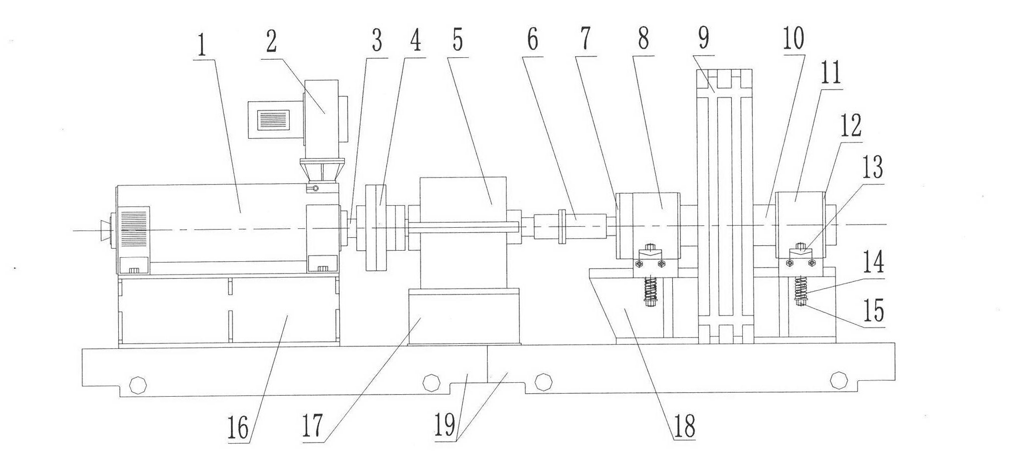
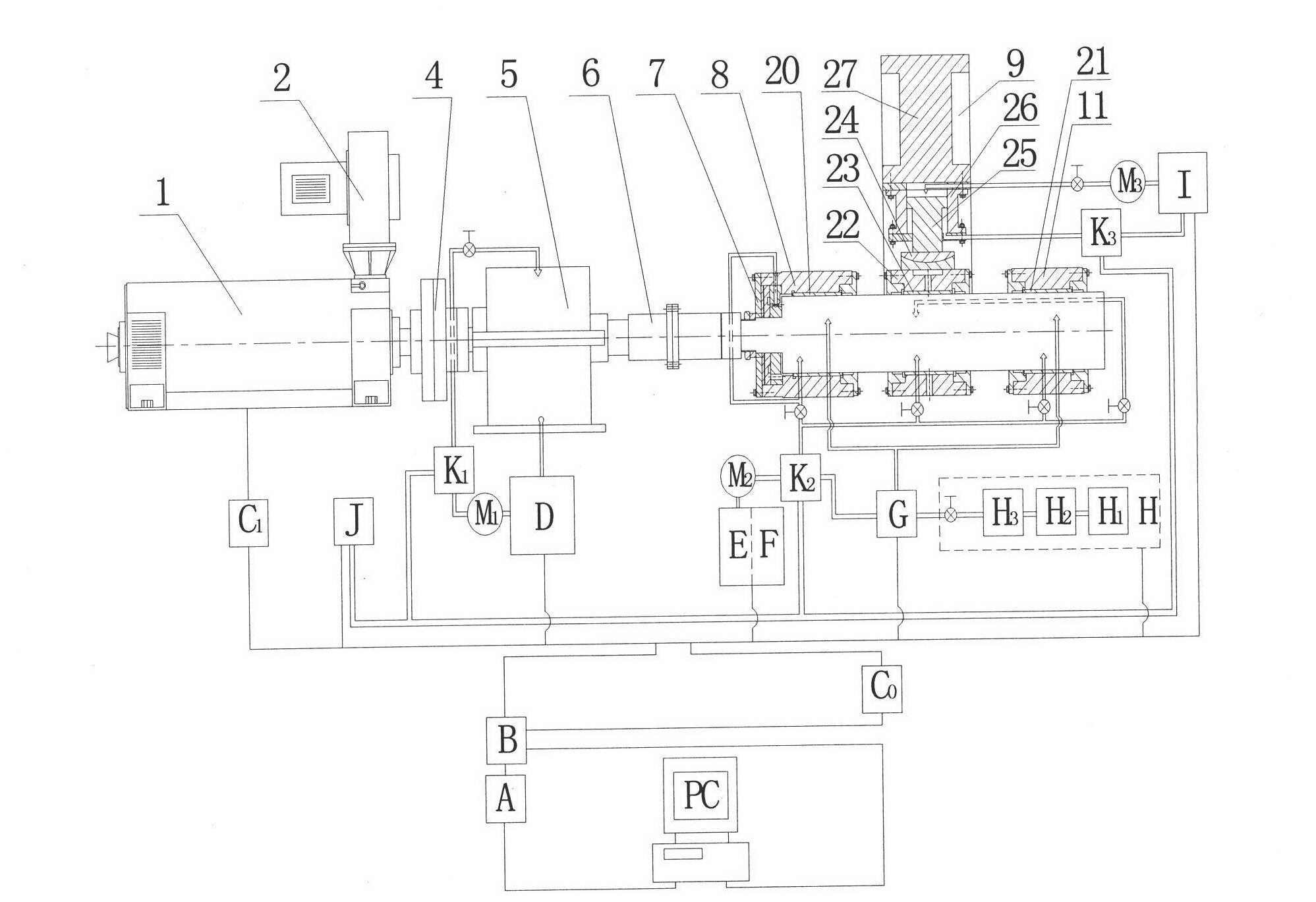
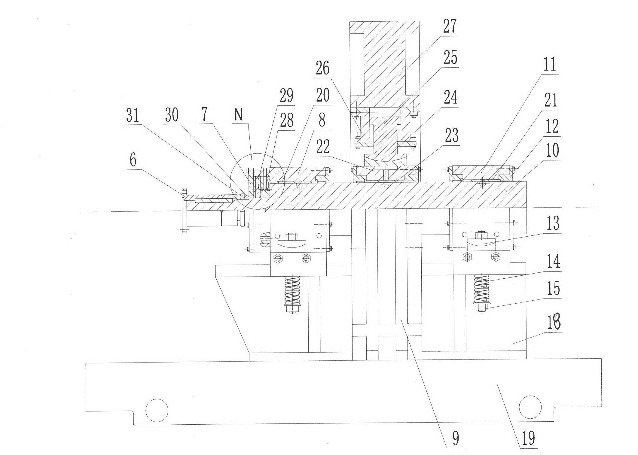
[0027] Such as figure 1 , figure 2 , image 3As shown, the bearing blocks 8, 11 are fixed on the base 18, the speed increaser 5 is installed on the base 17, the motor 1 is installed on the base 16, and the bases 16, 17, 18 can be placed on the horizontal slide table 19 Move and adjust left and right, fill cement below the horizontal slide table 19 to strengthen and resist vibration, and the dynamic pressure oil film bearing 23 and the left and right dynamic and static pressure oil film bearings 20, 21 are installed on the main shaft 10, and are installed on the respective corresponding dynamic pressure bearing seats 22 and the left and right dynamic and static pressure bearings together. Press the bearing seats 8 and 11, and then connect the main shaft 10 with the motor 1 on which the fan 2 is installed through the rigid coupling 6, the speed increaser 5 with a speed ratio of 1:8 and the elastic coupling 4, and ensure that the main shaft 10 and the motor shaft 3 of the moto...


PUM


Abstract

The invention discloses a comprehensive test-bed for an oil film bearing of a rolling mill, belonging to the technical field of testing equipment of oil film bearings of rolling mills. The comprehensive test-bed is characterized by comprising a mechanical system, a motor driving system, a hydraulic loading system, a lubricating system, an air pressure control system, an electric control system and a computer data acquisition system which are combined to form an integral and uniform operation; flow sensors, temperature sensors, pressure sensors and displacement sensors mounted on the bearing and all pipelines are connected to the computer data acquisition system through a PLC (Programmable Logic Controller); and the electric control system is connected with and controls the motor driving system, the hydraulic loading system, the lubricating system and the air pressure control system. The invention realizes integration of an electromechanical hydropneumatic integral system by setting rotation speed of a motor shaft and the dynamically controlling rolling conditions of the hydraulic load and testing performance of the oil film bearing of the rolling mill by the data acquisition system. The system has the advantages of compact structure and convenience for operation, and is suitable for the fields of various teaching and scientific research.

Description

Technical field: [0001] The invention belongs to the technical field of oil film bearing test equipment, in particular to a rolling mill oil film bearing comprehensive test stand. Background technique: [0002] Rolling mill oil film bearings have the characteristics of large load capacity, strong impact resistance, long service life, and high running precision. They are widely used in various plate and strip rolling mills and wire rolling mills, especially for automatic control of plate shape and plate thickness. on the large strip continuous rolling mill. [0003] At present, the existing bearing test benches at home and abroad are only used to measure the characteristic parameters of sliding bearings and rolling bearings. It is difficult to truly simulate the changes in the characteristic parameters of large-scale rolling mill oil film bearings under high-speed and heavy-duty rolling conditions, let alone fully reflect the differences. Influence of rolling conditions on t...

Claims


Application Information

Patent Timeline
Patent Type & Authority Applications(China)
IPC IPC(8): G01M13/04
Inventor 王建梅朱琳李海滨赵春江黄庆学黄讯杰薛涛康建峰
Owner TAIYUAN UNIVERSITY OF SCIENCE AND TECHNOLOGY
Why Eureka
Try Eureka