Coke oven checker brick mounting device and construction method therefor
An installation device and technology of checker bricks, which are applied in coking oven bricklaying operations, etc., can solve the problems that checker bricks cannot be installed to the top at one time, cumbersome installation of checker bricks, and low efficiency, so as to achieve simple and quick implementation, ensure penetration rate, and improve The effect of work efficiency
- Summary
- Abstract
- Description
- Claims
- Application Information
AI Technical Summary
Problems solved by technology
Method used
Image

Examples
Embodiment Construction
[0035] Various embodiments of the invention will be described in more detail below with reference to the accompanying drawings. In the various drawings, the same elements are denoted by the same or similar reference numerals. For the sake of clarity, various parts in the drawings have not been drawn to scale.
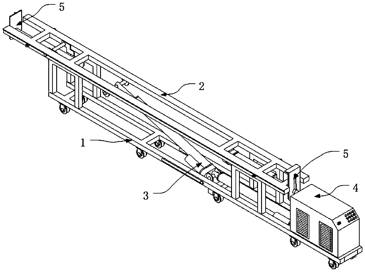
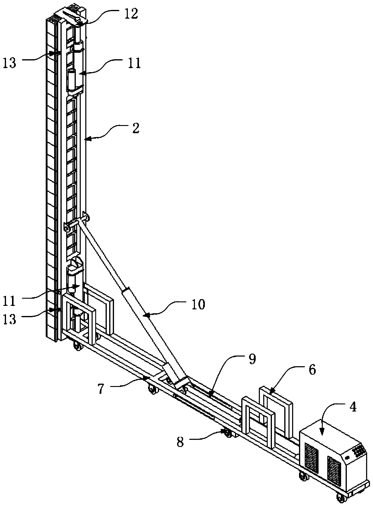
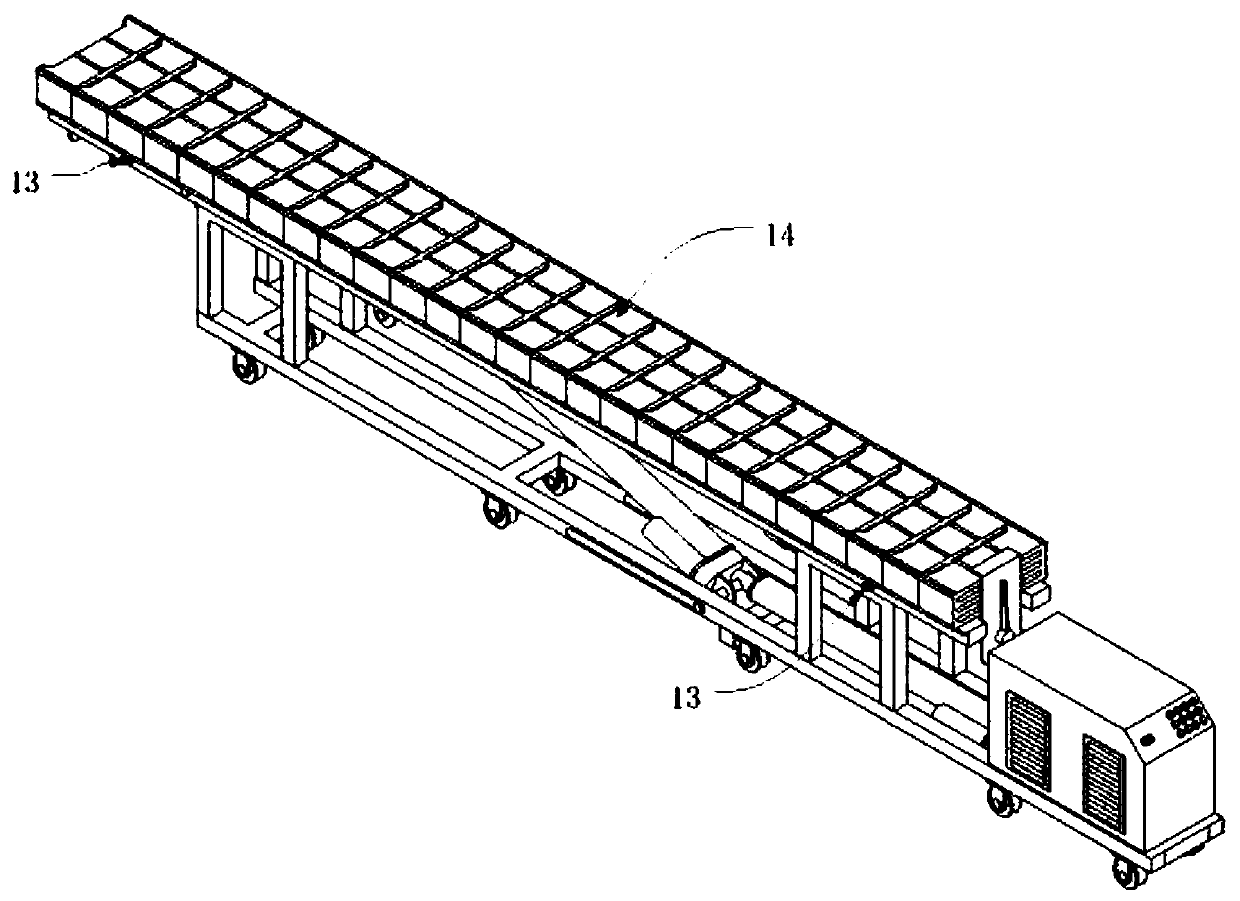
[0036] In the prior art, because of the limited space in the coke oven regenerator, the coke oven checker bricks are generally transported and installed in the form of spreaders and slide rails, but the use of spreaders and slide rails cannot place the checker bricks 14 once Installed to the top, manual handling is still required to complete the installation. Waste more manpower and working time, simultaneously to the installation of checker brick 14 will guarantee that the hole on the brick is aligned, more personnel operate, have reduced the penetration rate of checker brick 14.
[0037] The following will be combined with figure 1 to attach Figure 5 The present ...
PUM
 Abstract
Description
Claims
Application Information
 - Generate Ideas
- Intellectual Property
- Life Sciences
- Materials
- Tech Scout
- Unparalleled Data Quality
- Higher Quality Content
- 60% Fewer Hallucinations
Browse by: Latest US Patents, China's latest patents, Technical Efficacy Thesaurus, Application Domain, Technology Topic, Popular Technical Reports.
© 2025 PatSnap. All rights reserved.Legal|Privacy policy|Modern Slavery Act Transparency Statement|Sitemap|About US| Contact US: help@patsnap.com