Pulling riveting fastener

A firmware and riveting technology, applied in the direction of rivets, etc., can solve the problems of inability to meet the needs of fastening processing, single function, and inability to effectively determine the completion status of fastening operations.

Pending Publication Date: 2019-08-20
MEISHAN CRRC FASTENING SYST CO LTD
View PDF0 Cites 2 Cited by
  • Summary
  • Abstract
  • Description
  • Claims
  • Application Information

AI Technical Summary

Problems solved by technology

[0003] The existing blind rivets are simple to fasten and have a single function. During the fastening operation, it is often impossible to e

Method used


Image

  • Pulling riveting fastener
  • Pulling riveting fastener
  • Pulling riveting fastener

Examples


Embodiment Construction

[0031] The present invention is further described below in conjunction with specific embodiment, and specific embodiment is the further description of the principle of the present invention, does not limit the present invention in any way, and the identical or similar technology of the present invention all does not exceed the scope of protection of the present invention.

[0032] In conjunction with the accompanying drawings.

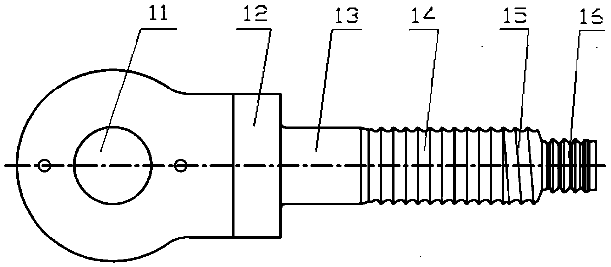
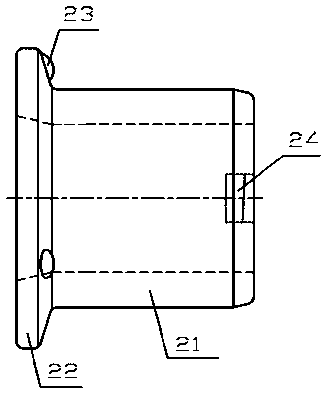
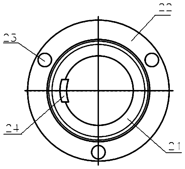
[0033] The blind rivet fastener is composed of a blind rivet 1 and a collar 2. The blind rivet 1 and the collar 2 adopt clearance fit. The blind rivet 1 includes an eye ring 11, a platform stage 12, a polished rod section 13, a locking Groove segment and grip groove segment 16 ; the collar 2 includes an integral flange segment 22 and a straight segment 21 .

[0034] The locking groove section consists of a ring groove section 14 and / or a threaded groove section 15 .

[0035] The eye ring is a through hole arranged on the head of the blind rivet 1 and ...


PUM


Abstract

The invention discloses a pulling riveting fastener. The pulling riveting fastener is composed of a pulling rivet and a lantern ring, wherein the pulling rivet and the lantern ring are in clearance fit; the pulling rivet comprises an eye ring, a step section, a polish rod section, a locking groove section and a grasping groove section which are integrally and sequentially arranged; the lantern ring comprises a flange section and a straight barrel section which are integrated; the locking groove section is composed of a ring groove section and/or a threaded groove section; the eye ring is a through hole which is formed in the head of the pulling rivet and is perpendicular to an axial direction of the pulling rivet; convex points higher than a ring surface are arranged at intervals on the ring surface at the side, connected with the straight barrel section, of the flange section of the lantern ring; a clamping gear with a groove structure is arranged on the inner wall of the straight barrel section of the lantern ring. According to the pulling riveting fastener, the eye ring, the fastener and a workpiece are of an integrated structure, a compact pulling rivet structure is formed by the step section, the polish rod section, the ring groove section, the threaded groove section and the grasping groove section, the clamping gear structure can be screwed into the locking threaded section of the rivet, and then the lantern ring and the rivet are pre-assembled together; and the convex point structure is used as an indication mark of qualified extrusion deformation length, so that fastening operation can be more conveniently and accurately controlled.

Description

technical field [0001] The invention belongs to the technical field of riveting, in particular to the design and manufacture of a rivet riveting fastener for connecting composite plates or metal plates, and belongs to riveting (B21J) and fasteners (F16B) of metal machining. Background technique [0002] Blind rivets are commonly used fastening joints in the existing fastening connection methods, and are generally used for the connection of parts that need to be bolted or riveted. When using the fastening operation, use special equipment for rivets to clamp the two parts to be combined, squeeze the metal of the annular collar and fill the pits of the multiple annular grooves of the bolt, so that the collar and the The pegs are tightly combined and fastened. Blind rivet fasteners have the same fastening force and never loosen after assembly. [0003] The existing blind rivets are simple to fasten and have a single function. During the fastening operation, it is often impossi...

Claims


Application Information

Patent Timeline
IPC IPC(8): F16B19/05
CPCF16B19/05
Inventor 徐建平刘宇邓涛贾云龙范亚峰肖长玖董帅张钦杨旭张威代广成
Owner MEISHAN CRRC FASTENING SYST CO LTD
Why Eureka
Try Eureka