A method and apparatus for beam failure recovery

A beam, user equipment technology, applied in the field of communications

Active Publication Date: 2019-08-20
VIVO MOBILE COMM CO LTD
View PDF2 Cites 10 Cited by
  • Summary
  • Abstract
  • Description
  • Claims
  • Application Information

AI Technical Summary

Problems solved by technology

[0003] An object of the embodiments of the present invention is to provide a method and device for beam failure recovery to solve the proble

Method used


Image

  • A method and apparatus for beam failure recovery
  • A method and apparatus for beam failure recovery
  • A method and apparatus for beam failure recovery

Examples


example 1

[0126] Example 1: Two cell wireless network temporary identities are monitored, and one can be discarded later.

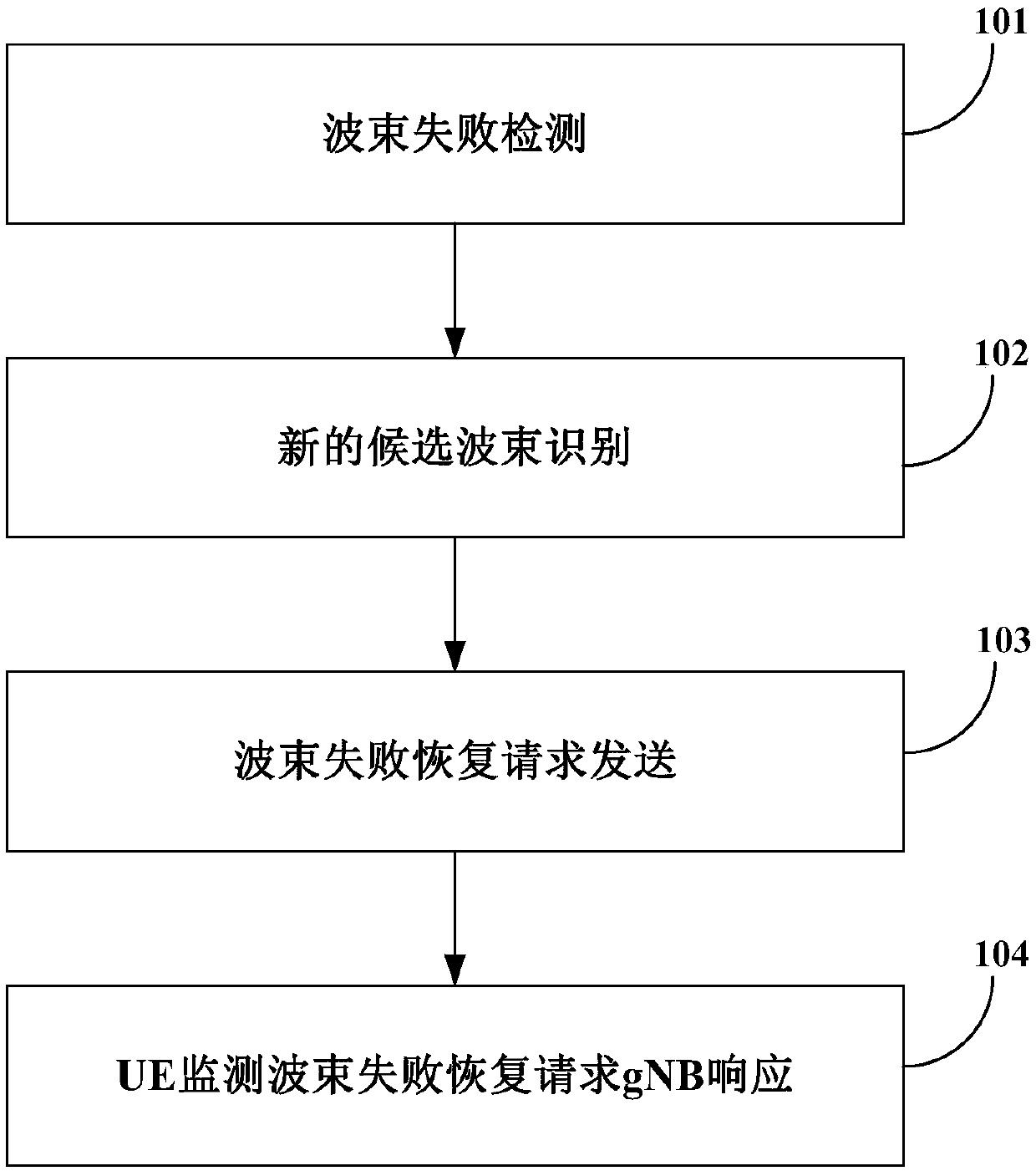
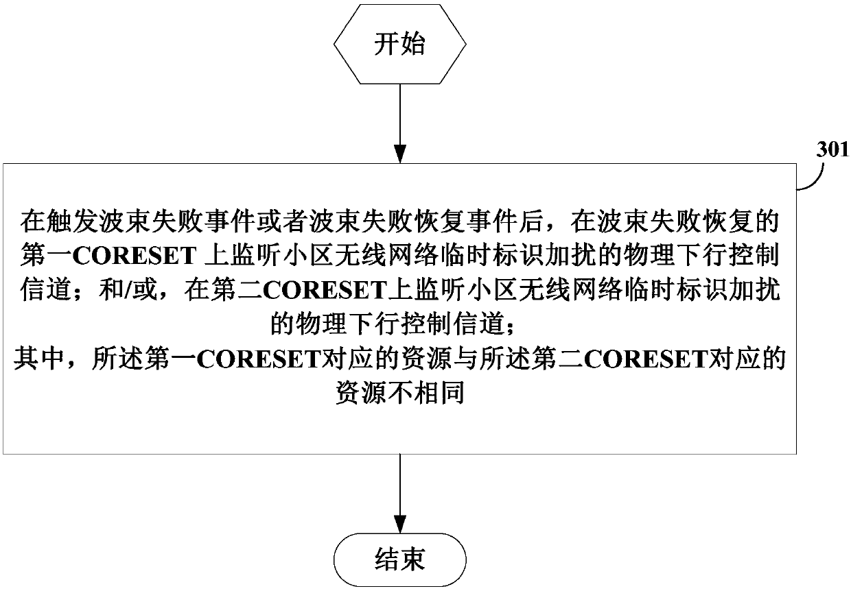
[0127] After a beam failure event is triggered or a beam failure is recovered, the UE behavior includes at least one of:

[0128] (1) Monitor the physical downlink control channel scrambled by the wireless network temporary identifier of the cell on the first control channel resource set CORESET of beam failure recovery.

[0129] (2) Monitor the physical downlink control channel scrambled by the wireless network temporary identity of the cell on the second CORESET.

[0130] Further, before the above actions (1) and (2) occur in the UE, the media access control (Media Access Control, MAC) layer instructs the physical (Physical, PHY) layer to indicate that a beam fails. After receiving the instruction, the PHY layer executes the above actions (1) and (2).

[0131] Furthermore, before the above behaviors (1) and (2) occur on the UE, the UE sends a beam failure recov...

example 2

[0135] Example 2: monitor two C-RNTIs, further, do not send a preamble code to the network side device, or monitor two C-RNTIs after preamble.

[0136] After a beam failure event is triggered or a beam failure is recovered, the UE behavior includes at least one of:

[0137] (1) Monitor the physical downlink control channel scrambled by the wireless network temporary identifier of the cell on the first control channel resource set CORESET of beam failure recovery.

[0138] (2) Monitor the physical downlink control channel scrambled by the wireless network temporary identity of the cell on the second CORESET.

[0139] Scenario 1: When the cell wireless network temporary identity is monitored on the second CORESET, the UE behavior includes at least one of:

[0140] The UE continues (does not stop) the beam failure recovery procedure;

[0141] The UE continues (does not stop) the random access process in the beam failure recovery process;

[0142] The PHY layer indicates to the...

example 3

[0166] During the RACH procedure in the beam failure recovery procedure, the UE behavior includes at least one of:

[0167] (1) When the non-competitive random access fails, directly declare that beam failure recovery fails, or use CBRA to continue the random access process of beam failure recovery.

[0168] The failure of the non-contention random access includes: the timer of the non-contention-free random access (CFRA) expires and / or the counter of the CFRA reaches the maximum value. That is, when using contention-based random access (Contention-based random access, CBRA) to continue the random access process of beam failure recovery, if the CBRA timer expires and / or after the CBRA counter counts to the maximum value, directly declare Beam failure recovery failed.

[0169] (2) When non-competitive random access fails and no indication of candidate beams and / or candidate resources of the physical layer is received, declare beam failure recovery failure, or use CBRA to conti...


PUM


Abstract

The embodiment of the invention provides a method and apparatus for beam failure recovery, and the method comprises the steps: monitoring a physical downlink control channel scrambled by a cell wireless network temporary identifier on a first control channel resource set CORESET of beam failure recovery after a beam failure event or a beam failure recovery event is triggered; and/or monitoring a physical downlink control channel scrambled by the cell wireless network temporary identifier on the second CORESET; wherein the resource corresponding to the first CORESET is different from the resource corresponding to the second CORESET.

Description

technical field [0001] The embodiments of the present invention relate to the technical field of communications, and in particular to a method and device for recovering from beam failure. Background technique [0002] In the prior art, after the beam failure trigger (Beam failure trigger), the user equipment ((User Equipment, UE) will not continue to monitor (monitor) except the candidate beam (candidate beam), or the reference signal (Reference Signal) corresponding to the candidate beam. Signal, RS) other beams or other beams corresponding to the RS control channel resource set (Control Channel Resource Set, CORESET) cell radio network temporary identifier (CellRadio Network Temporary Identifier, C-RNTI). Contents of the invention [0003] An object of the embodiments of the present invention is to provide a beam failure recovery method and device to solve the problem of whether the user equipment needs to monitor the C-RNTI scrambled PDCCH in the specified CORESET durin...

Claims


Application Information

Patent Timeline
IPC IPC(8): H04L5/00H04W16/28H04W74/00H04W74/08
CPCH04L5/0053H04W16/28H04W74/008H04W74/0833H04L5/0048H04B7/088H04B7/0695H04W76/19H04B7/06966H04W72/046H04W74/006H04W72/54H04W72/563
Inventor 陈力吴昱民梁敬
Owner VIVO MOBILE COMM CO LTD
Why Eureka
Try Eureka