Machine core support

A technology of movement support and support plate, applied in the field of support, can solve the problems of affecting the air volume of the first air duct, failing to achieve heat dissipation effect, affecting the heat dissipation effect of the movement, etc., to achieve the effect of improving heat dissipation effect and accelerating wind speed

Active Publication Date: 2019-08-20
SHANGHAI HUGONG ELECTRIC WELDING MACHINE MFG
View PDF14 Cites 0 Cited by
  • Summary
  • Abstract
  • Description
  • Claims
  • Application Information

AI Technical Summary

Problems solved by technology

[0005] The fan of the above-mentioned patent is not installed on the machine core support, but is installed on the chassis; the first air duct communicates with the heat dissipation channel formed by the fan through the air inlet opened on the machine core support, and is limited by the air inlet It will directly affect the air volume in the first air duct and thus affect the cooling effect of the movement
If the heat dissipation object of the first air duct is larger than the heat dissipated by the core, the heat dissipated by the first air duct is far from achieving the cooling effect

Method used


Image

  • Machine core support
  • Machine core support
  • Machine core support

Examples


Embodiment Construction

[0039] The present invention will be described in further detail below in conjunction with the accompanying drawings.

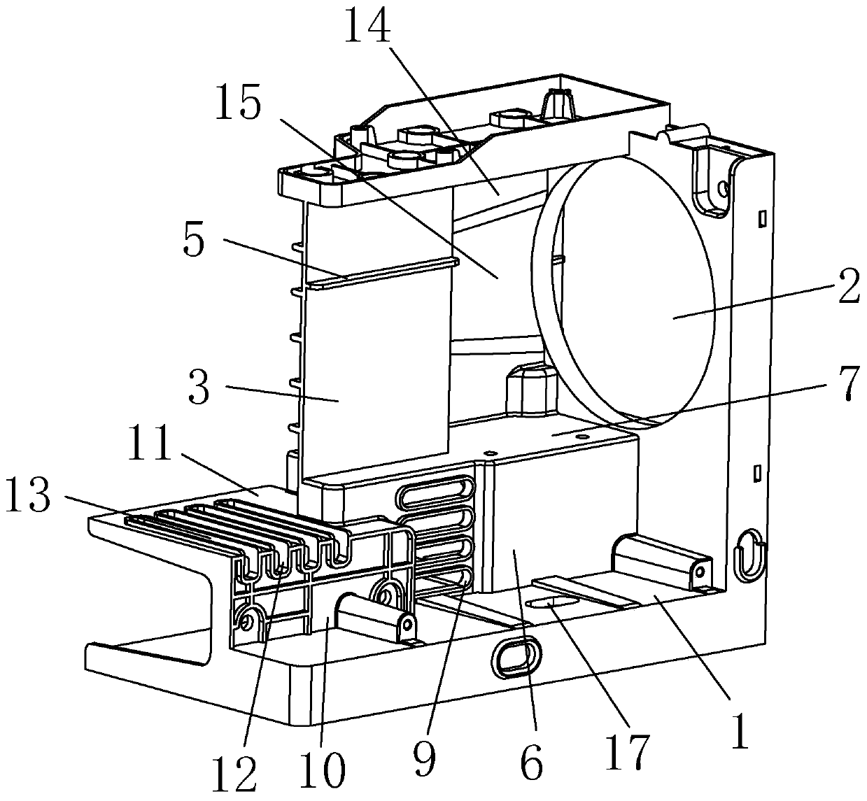
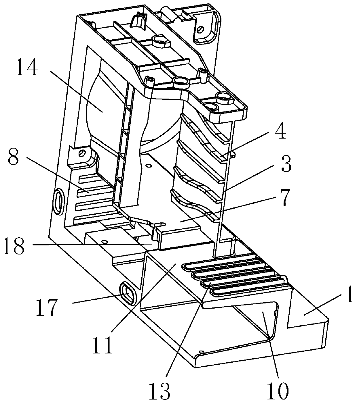
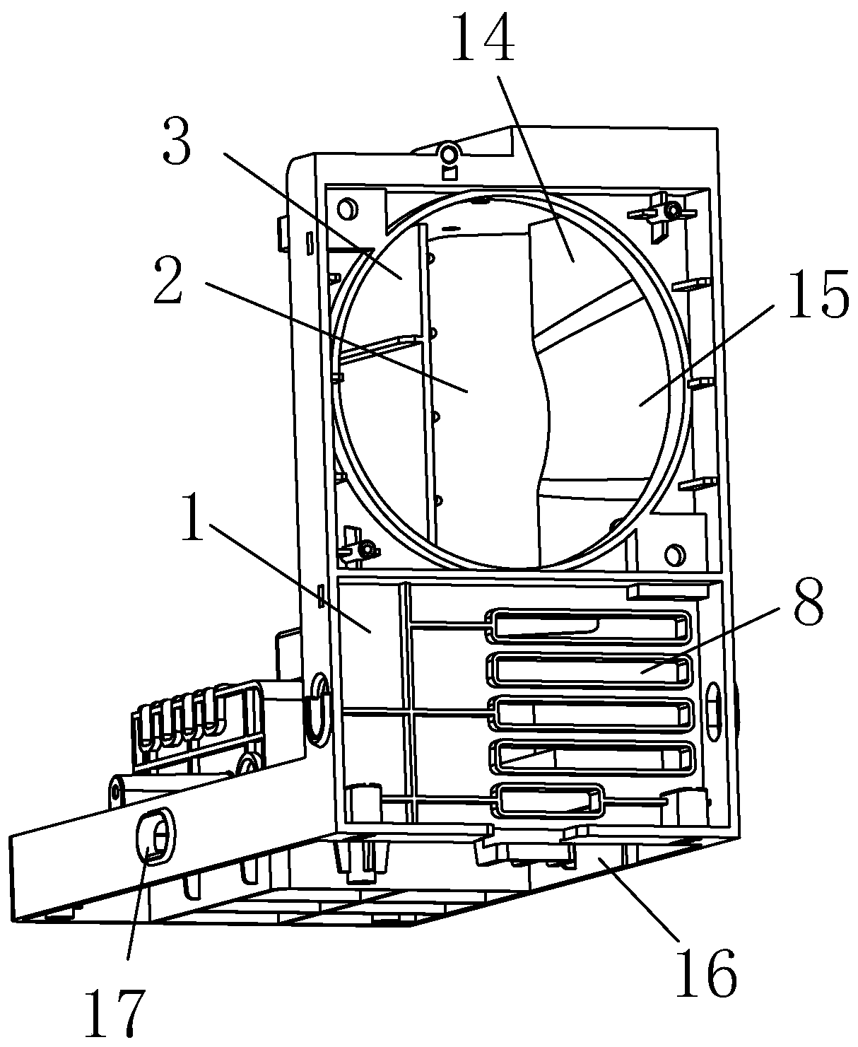
[0040] refer to figure 1 , is a movement support disclosed by the present invention, including an L-shaped base 1, a circular air inlet 2 is opened on the vertical plate of the L-shaped base 1, and a fan is installed on the air inlet 2 in this embodiment. A first mounting plate 6 is vertically installed on the horizontal plate of the L-shaped base 1 below the air inlet 2 , and one end of the first mounting plate 6 is vertically connected to the vertical plate of the L-shaped base 1 . The first mounting plate 6 away from the end connected to the horizontal plate of the L-shaped base 1 is vertically connected to one end of the first supporting plate 7 , and the first supporting plate 7 is arranged parallel to the horizontal plate of the L-shaped base 1 .

[0041] refer to figure 2 , A first inner cavity is formed between the base 1 , the first mounting plate...


PUM


Abstract

The invention relates to the technical field of supports. Movement support, the device comprises a base, an air inlet is formed in the base; a flow guide plate is installed on the base on one side ofthe air inlet, a first heat dissipation flow channel communicated with the air inlet is formed in the base on one side of the flow guide plate, a second heat dissipation flow channel communicated withthe air inlet is formed in the base on the other side of the flow guide plate, and the first heat dissipation flow channel and the second heat dissipation flow channel between the flow guide plate and the air inlet are communicated. The first heat dissipation flow channel and the second heat dissipation flow channel are directly communicated with the air inlet, and the flow guide plate only guides the air inlet amount from the air inlet, so that the non-ideal local heat dissipation effect is reduced, and it is guaranteed that the air inlet amount from the air inlet can fully dissipate heat.

Description

technical field [0001] The invention relates to the technical field of brackets, in particular to a movement bracket. Background technique [0002] The inverter welding machine rectifies and filters the three-phase or single-phase 50Hz power frequency AC to obtain a smoother DC. The inverter circuit composed of IGBT or field effect tube converts the DC into 15-100kHz AC. After the main transformer is stepped down, it is rectified and filtered again to obtain a stable DC output welding current (or re-inverted to output AC with the required frequency). The control circuit of the inverter welding and cutting equipment is composed of a given circuit and a drive circuit. By processing the feedback of voltage and current signals, the cycle control of the whole machine is realized. The control technology of pulse width modulation (PWM) is used as the core to obtain a fast pulse. Widely modulated constant current characteristics and excellent welding and cutting process effects. ...

Claims


Application Information

Patent Timeline
Patent Type & Authority Applications(China)
IPC IPC(8): H05K7/20H05K7/14
CPCH05K7/20145H05K7/14B23K9/1006B23K37/003B23K37/0282
Inventor 不公告发明人
Owner SHANGHAI HUGONG ELECTRIC WELDING MACHINE MFG
Why Eureka
Try Eureka