Crushing and compressing treatment device for woody wastes of construction engineering
A technology of compression treatment device and construction engineering, applied in grain processing, manufacturing tools, wood processing utensils and other directions, can solve the problems of large smoke and dust pollution, no recycling, inconvenient transportation and collection, etc. Effect
- Summary
- Abstract
- Description
- Claims
- Application Information
AI Technical Summary
Problems solved by technology
Method used
Image
Examples
Embodiment 1
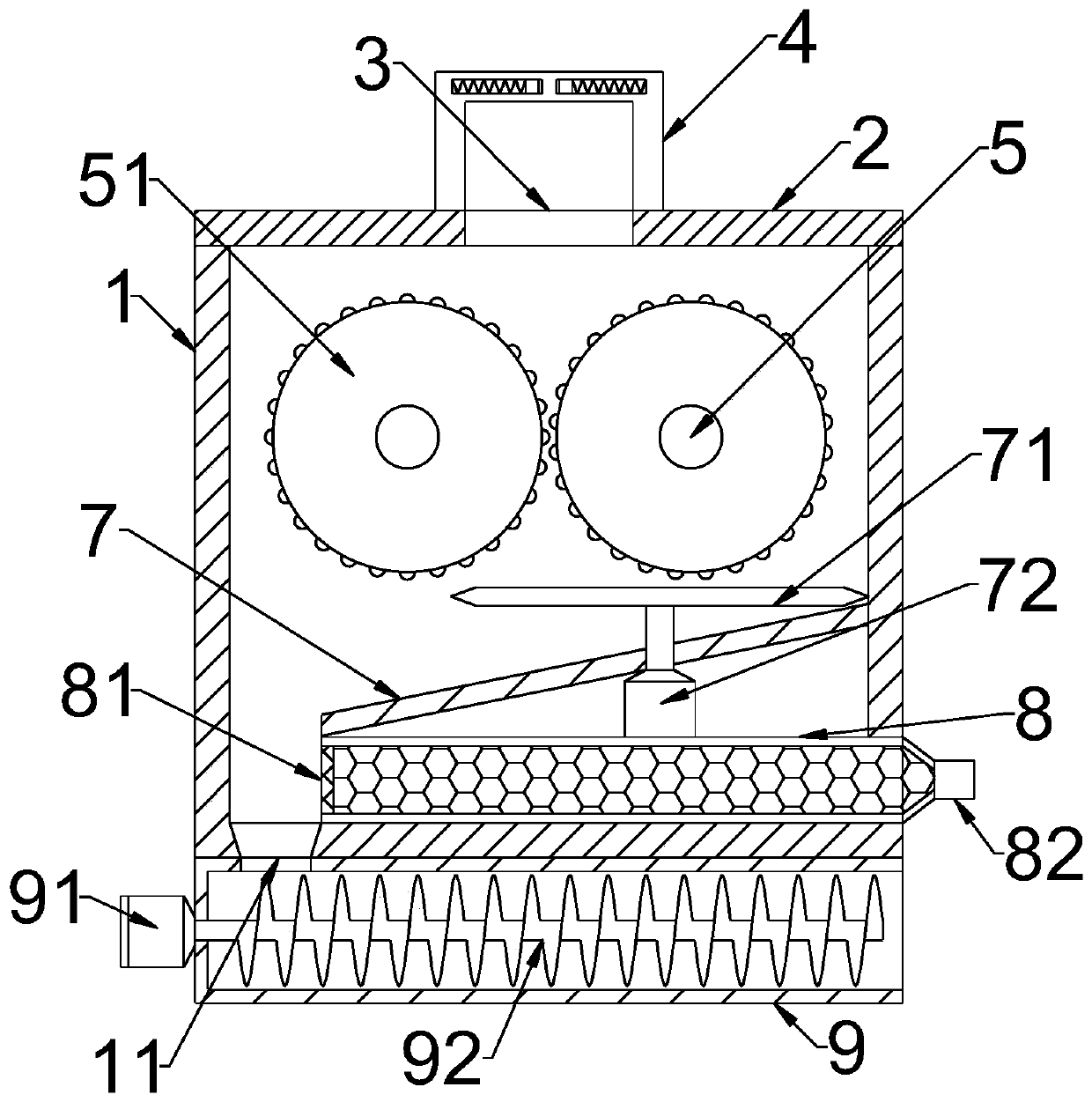
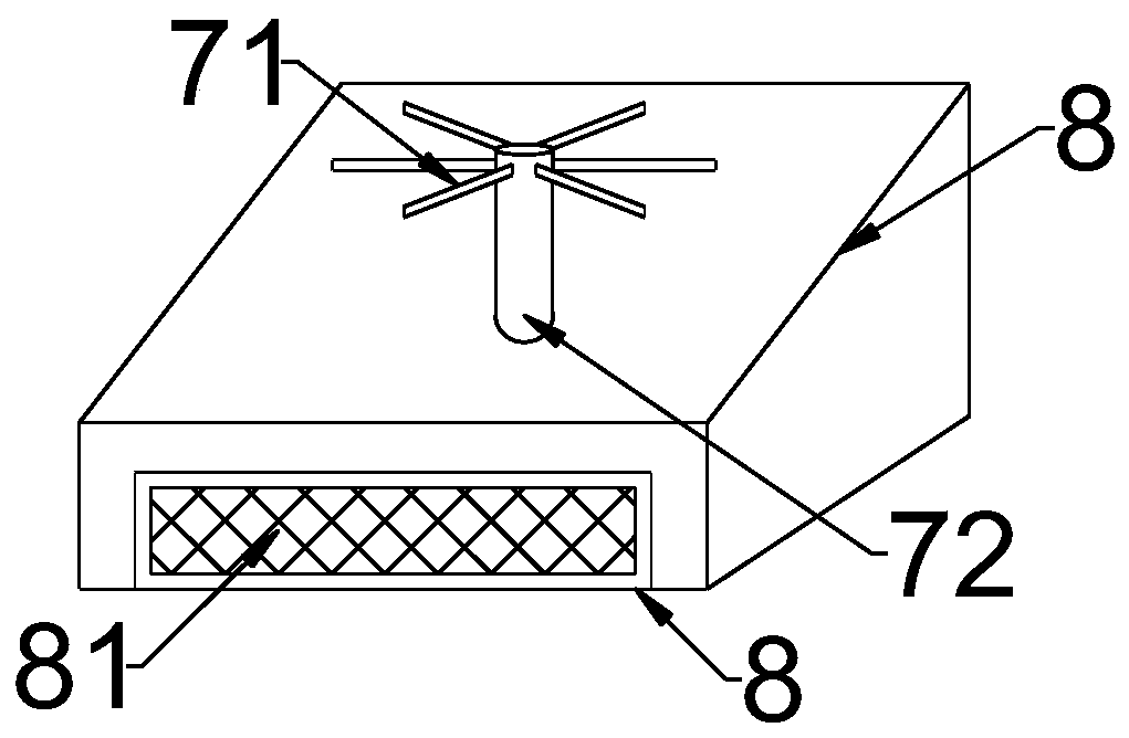
[0023] see Figure 1~3 , in an embodiment of the present invention, a device for crushing and compressing woody waste in construction projects includes a housing 1, a rolling roller 51 disposed on the housing 1, a material guide mechanism 7, and a material guide mechanism 7 connected to the lower end of the housing 1 to pass through the material guide. The material guide base 9 connected to the hole 11, the upper end of the housing 1 is movably connected with an upper cover 2, the upper cover 2 is provided with a feed port 3, and a material guide frame is provided above the feed port 3 4. A dust suction chamber 8 for collecting fine wood powder is also movably assembled in the housing 1 .
[0024] Between the front and rear side walls of the housing 1 are rotatably connected through the drive shaft 5, and a symmetrical rolling roller 51 is provided. The surface of the rolling roller 51 is densely covered with integrally formed protrusions, which are arc-shaped protrusions. Or...
Embodiment 2
[0031] see Figure 4, in the embodiment of the present invention, a device for crushing and compressing wooden waste in construction engineering, on the basis of embodiment 1, the material guide frame 4 is a "door" type metal piece symmetrically arranged on both sides of the feed port 3, Both sides of the horizontal part of the material guide frame 4 are symmetrically embedded with slide grooves 41, the openings of the slide grooves 41 on the material guide frames 4 on both sides are oppositely arranged, and the relative slide grooves 41 between the material guide frames 4 on both sides are symmetrically slid to fit A sliding rod 42 is provided, and the sliding rod 42 is elastically connected to the inner wall of the sliding groove 41 through a spring, and the periphery of the sliding rod 42 is rotationally connected with a limit roller 43, and the limit roller 43 is located on the material guide frame on both sides. 4, the limit roller 43 is an hourglass-shaped roller with a ...
PUM
 Abstract
Description
Claims
Application Information
 - R&D
- Intellectual Property
- Life Sciences
- Materials
- Tech Scout
- Unparalleled Data Quality
- Higher Quality Content
- 60% Fewer Hallucinations
Browse by: Latest US Patents, China's latest patents, Technical Efficacy Thesaurus, Application Domain, Technology Topic, Popular Technical Reports.
© 2025 PatSnap. All rights reserved.Legal|Privacy policy|Modern Slavery Act Transparency Statement|Sitemap|About US| Contact US: help@patsnap.com


