
Device for adjustment of a printhead

A technology of printing heads and equipment, applied in printing, general parts of printing machinery, printing machines, etc., to avoid overshoot or undershoot, and achieve the effect of accurate calibration

Active Publication Date: 2019-08-23
HEIDELBERGER DRUCKMASHINEN AG
View PDF12 Cites 0 Cited by
  • Summary
  • Abstract
  • Description
  • Claims
  • Application Information

AI Technical Summary

Problems solved by technology

[0004] Furthermore, the accuracy is affected by the fact that the operator cannot always avoid overshooting during the adjustment or underadjustment (Untersteuern), since the rotation of the screw takes place steplessly (stufenlos)

Method used


Image

  • Device for adjustment of a printhead
  • Device for adjustment of a printhead
  • Device for adjustment of a printhead

Examples


Embodiment Construction

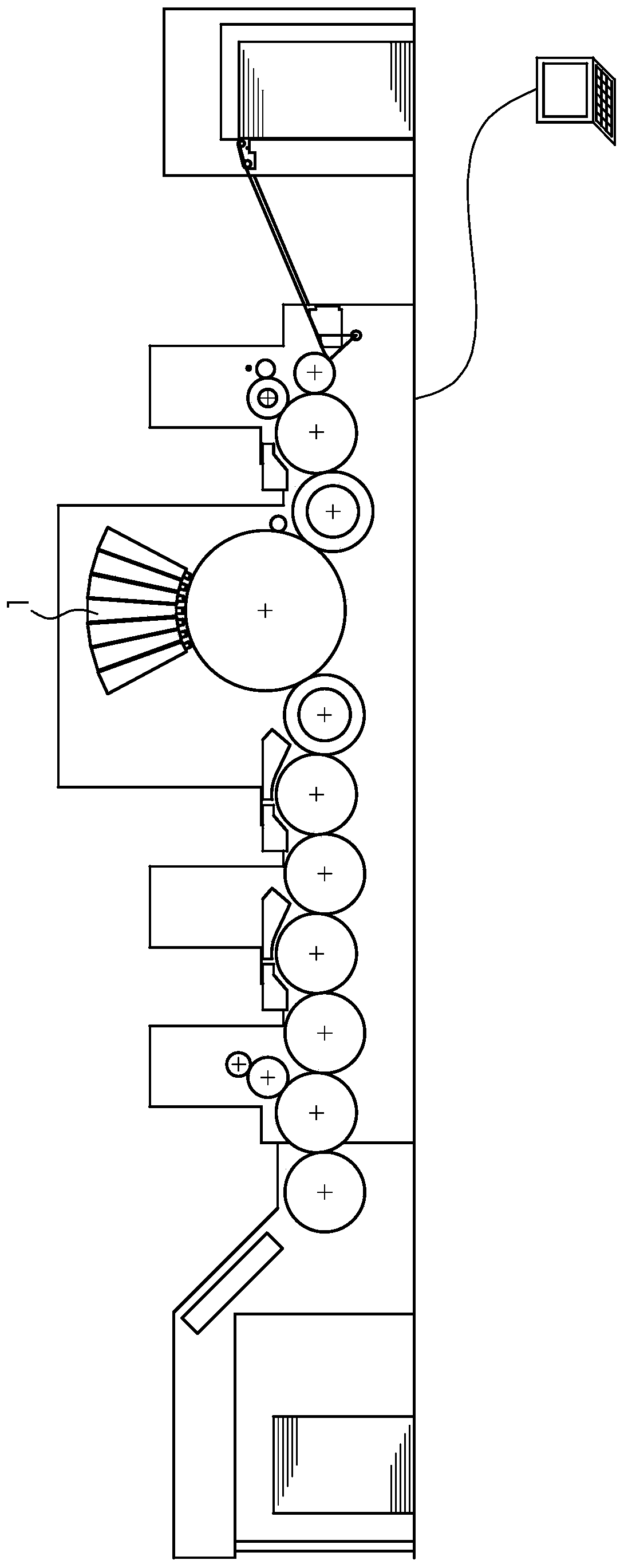
[0022] figure 1 A printing press with a plurality of printing beams 1 is shown for inkjet printing onto printing substrates made of paper or thick paper. The printing material is in the form of a sheet, but can also be in the form of a web. These printing beams 1 are identical in structure, so that only one printing beam 1 needs to be described. The printing beam 1 has printing heads 2 in an arrangement perpendicular to the figure 1 The graph plane extension of . The printing heads 2 are arranged to extend over the formatted width of the printing material, and the printing beam 1 is used for page-width printing.

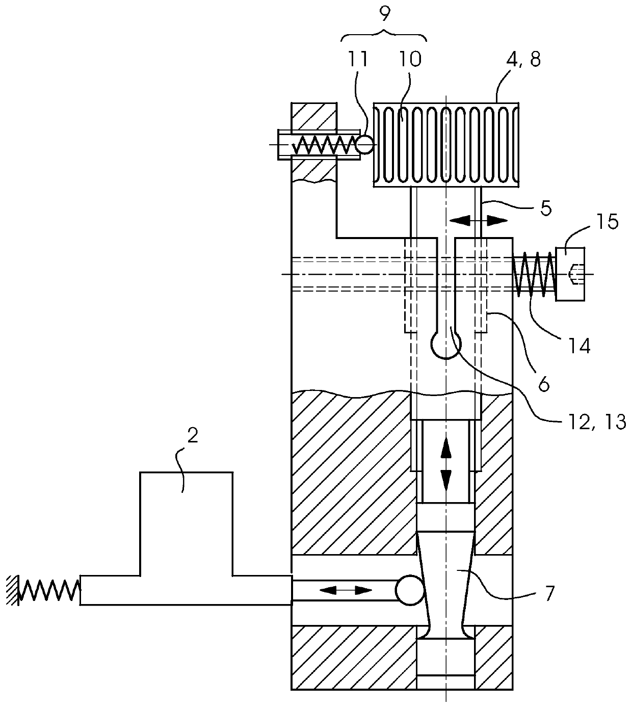
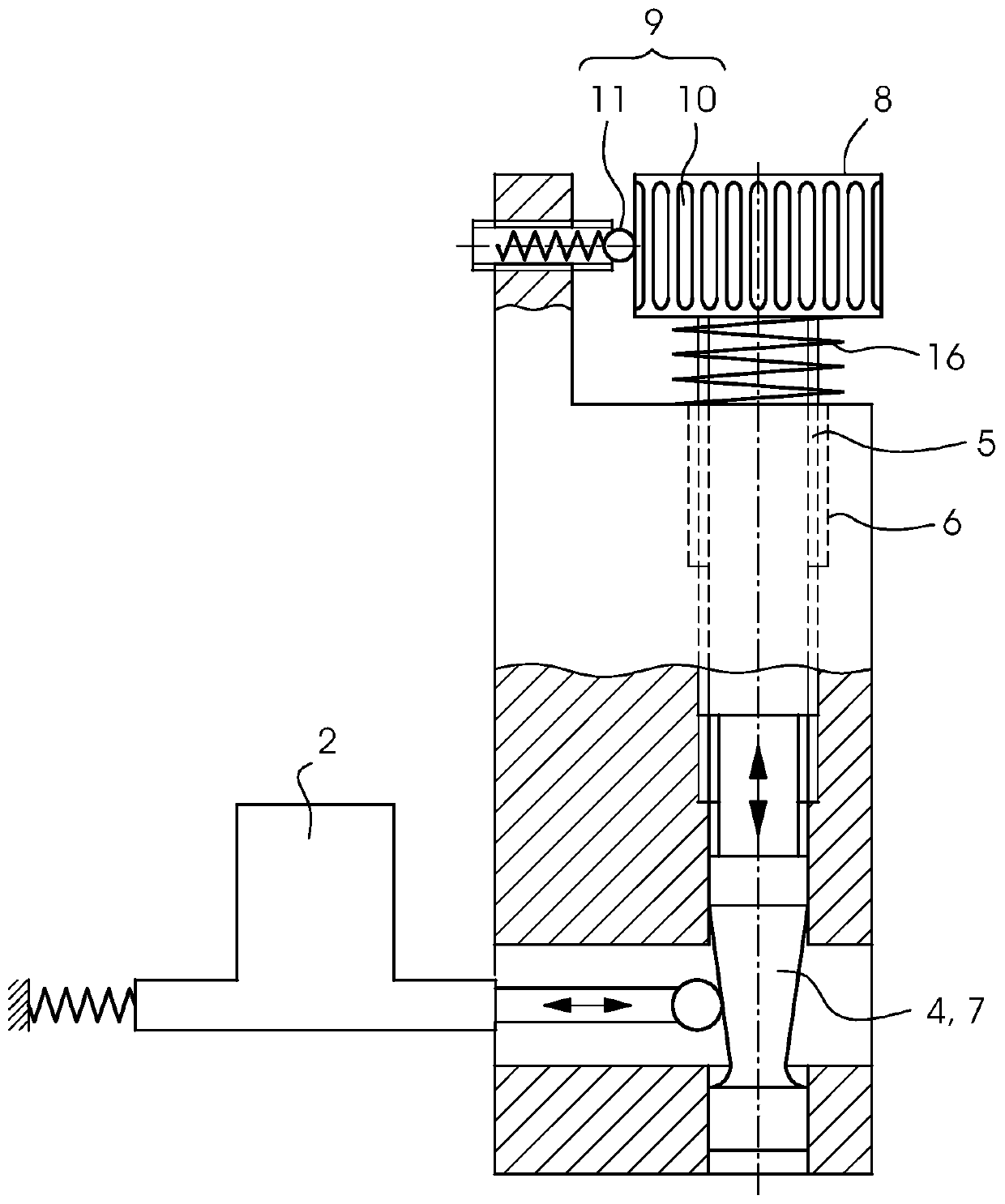
[0023] Each print head 2 is equipped with a calibration device by means of which a print head 2 can be adjusted relative to its adjacent print head 2 . This adjustment movement of the printing head 2 driven by the calibration device can be a translation or a rotation.

[0024] calibration equipment in figure 2 with image 3 The embodiments shown in have commo...


PUM


Abstract

The invention relates to a device for aligning a printhead (2). The device includes a holder (3) and a screwing member (4) having a tapered portion (7), the screwing member (4) being screwed into theholder (3), and the printhead (2) resting on the tapered portion (7). A spring (16) is provided for reducing a thread gap between the holder (3) and the screwing member (4), and a latching mechanism (9) is provided for determining the step width during rotation of the screwing member (4).

Description

technical field [0001] The invention relates to a device for calibrating a printing head, said device comprising a holder and a screw with a conical portion (Schraube), wherein the screw is screwed into the holder and the printing head rests on on the cone. Background technique [0002] In a printing beam with an arrangement of printing heads, it is necessary to align the printing heads with one another. For this purpose, calibration devices are used which each have a screw with a cone. The corresponding printing head rests directly or indirectly via an intermediate block on the cone. The cone forms a feather key transmission, which converts the axial movement of the screw into a radial movement of the printing head relative to the screw. [0003] One such calibration device is described in document US 2009 / 0147048 A1. The accuracy of the calibration device is influenced by the thread gap (ie the gap between the external thread of the screw and the internal thread of the...

Claims


Application Information

Patent Timeline
IPC IPC(8): B41J2/01B41J2/045B41J29/38B41J29/393B41F33/00
CPCB41F33/00B41J2/01B41J2/04505B41J29/38B41J29/393B41J25/001
Inventor A·米勒B·沃尔夫
Owner HEIDELBERGER DRUCKMASHINEN AG
Learn More