A Concrete Ultra-flat Floor Cut-Free Construction Structure

A concrete and floor technology, which is applied to the coagulation pavement, roads, buildings and other directions of on-site paving, can solve problems such as failure to meet building quality requirements, difficulty in grasping the time of cutting seams, and inability to cut seams in time, so as to avoid two problems. Secondary kerf, reduced shrinkage stress cracks, reduced uncontrollability effects

Active Publication Date: 2020-12-04
SCEGC NO 5 CONSTRUCTION ENGINEERING GROUP COMPANYLTD
View PDF7 Cites 0 Cited by
  • Summary
  • Abstract
  • Description
  • Claims
  • Application Information

AI Technical Summary

Problems solved by technology

[0002] With the rapid development of the economy, the demand for large workshops, electronic workshops, logistics warehouses and other buildings is increasing, and the requirements for the flatness of the ground and construction quality are becoming more and more stringent according to the functions. According to the "Quality Acceptance Specification" (GB50209-2002), the surface flatness of cement concrete is 5mm / 2m, which is far from meeting the quality requirements of building functions.
At present, the control of concrete surface flatness in the industry mainly depends on the actual construction level of the construction personnel, and the controllability is low; in addition, according to the performance of concrete and the requirements of national regulations, it is necessary to cut induction joints on the floor to prevent and reduce the occurrence of concrete cracks , the current industry practice is to use machinery to cut the joints after the concrete solidifies. Because it is difficult to grasp the cutting time, the joints cannot be cut in time after the concrete solidifies, resulting in shrinkage stress cracks

Method used


Image

  • A Concrete Ultra-flat Floor Cut-Free Construction Structure
  • A Concrete Ultra-flat Floor Cut-Free Construction Structure
  • A Concrete Ultra-flat Floor Cut-Free Construction Structure

Examples


Embodiment Construction

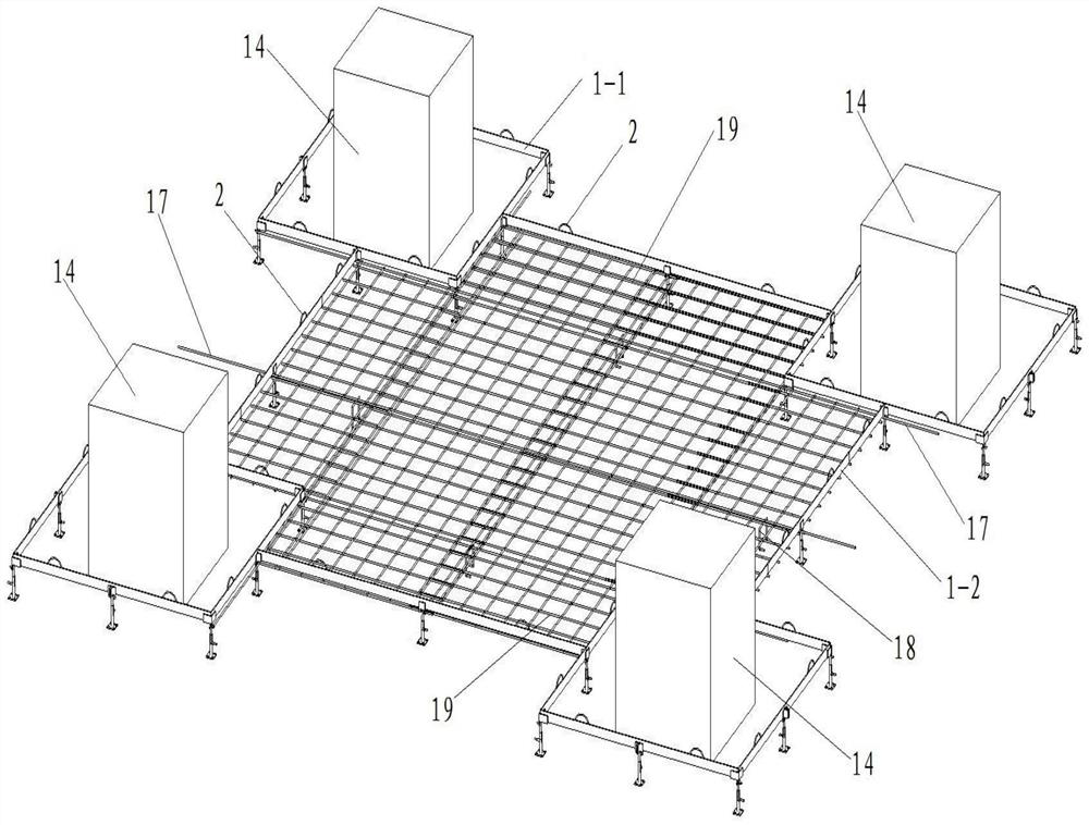
[0034] Such as Figure 1 to Figure 4 As shown, the present invention includes a concrete floor and a floor foundation poured in the concrete floor, the floor foundation includes a partition network and a floor reinforcement layer, and is used to support the partition network and The support mechanism of the floor reinforcement layer, the support mechanism includes a plurality of support rings arranged in an array, and in the support mechanism, between two adjacent support rings arranged in the same row and between two adjacent support rings arranged in the same row An auxiliary support frame is arranged between the support rings;

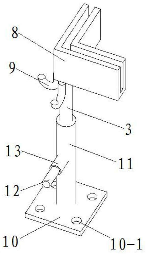
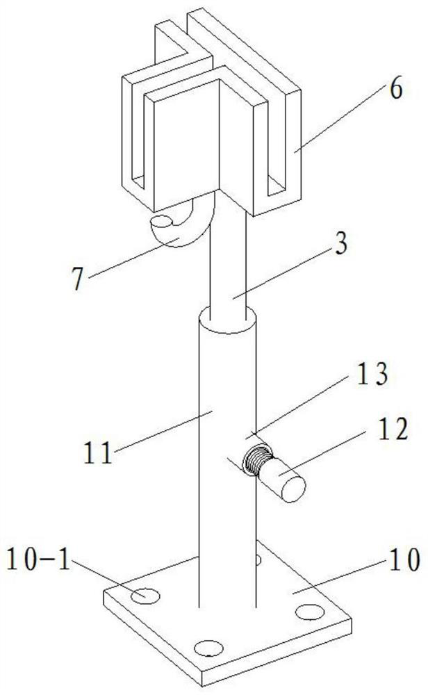
[0035] The support ring includes four matching main support frames, the four main support frames enclose a rectangular area, and a transition support frame is arranged between the two main support frames on the same side of the rectangular area, The main support frame includes an L-shaped clip 8 and a main adjustment base arranged below the L-shape...


PUM


Abstract

The invention discloses a non-slitting construction structure of a concrete super-flat terrace. The construction structure comprises a concrete terrace and a terrace foundation poured in the concreteterrace, wherein the terrace foundation comprises a partition plate network, a terrace steel bar layer, and a supporting mechanism for supporting the partition plate network and the terrace steel barlayer; the supporting mechanism comprises a plurality of supporting rings arranged in an array mode; and an auxiliary supporting frame is arranged between every two adjacent supporting rings arrangedin the same row and between every two adjacent supporting rings arranged in the same column in the supporting mechanism. According to the construction structure, the super-flat terrace is subjected tonon-slitting construction by arranging the partition plate network, the terrace steel bar layer and the supporting mechanism for supporting the partition plate network and the terrace steel bar layer; the height of main supporting frames, transition supporting frames and the auxiliary supporting frames can all be adjusted through adjustment bases so as control the elevation of the partition platenetwork; and the surface finishing operability is controlled by using the partition plate network, the uncontrollable property of concrete surface finishing is effectively reduced, and the smoothnessof the concrete surface is improved.

Description

technical field [0001] The invention belongs to the technical field of building construction, and in particular relates to a construction structure for super-flat concrete floors without cutting seams. Background technique [0002] With the rapid development of the economy, the demand for large workshops, electronic workshops, logistics warehouses and other buildings is increasing, and the requirements for the flatness of the ground and construction quality are becoming more and more stringent according to the functions. According to the "Quality Acceptance Specification" (GB50209-2002), the surface flatness of cement concrete is 5mm / 2m, which is far from meeting the quality requirements of building functions. At present, the control of concrete surface flatness in the industry mainly depends on the actual construction level of the construction personnel, and the controllability is low; in addition, according to the performance of concrete and the requirements of national re...

Claims


Application Information

Patent Timeline
Patent Type & Authority Patents(China)
IPC IPC(8): E01C7/14E01C5/08
CPCE01C5/08E01C7/14
Inventor 黄凯师小健齐浩常战祖田斐丁浩杨世异徐轩石涛王刚
Owner SCEGC NO 5 CONSTRUCTION ENGINEERING GROUP COMPANYLTD
Why Eureka
Try Eureka