Check patentability & draft patents in minutes with Patsnap Eureka AI!

Rotatable electrical connector

A technology of electrical connectors and rotating sleeves, applied in the direction of flexible/rotatable wire connectors, connections, two-part connecting devices, etc., can solve the problems of loosening of rotating sleeves, mutual separation, poor wear resistance, etc., to increase the sense of damping , The effect of convenient buckle and high structural strength

Pending Publication Date: 2019-08-23
广州亿威科技有限责任公司
View PDF1 Cites 0 Cited by
  • Summary
  • Abstract
  • Description
  • Claims
  • Application Information

AI Technical Summary

Problems solved by technology

[0002] At present, with the advancement of new energy technology, the types of electrical connectors are also improved. For example, the technical solution of Chinese patent ZL201510390015.8 discloses an electrical connector that can realize high-voltage connection and conduction, and can be rotated at any angle. , wherein the clamping convex ring 1-112 on the socket column 1-11 and the clamping groove of the rotatable body 1-2 cooperate with each other to realize the rotation of the rotatable body 1-2, and the clamping convex ring 1-112 is integrated It is set on the socket column 1-11 made of plastic material, and the clamping groove is set on the rotatable body 1-2 made of plastic material as a whole. The structure made of plastic material has low strength and poor wear resistance, and it is easy to appear convex after long-term use. The ring and the groove are separated from each other, so that the rotating sleeve is loose and the structure fails

Method used


Image

  • Rotatable electrical connector
  • Rotatable electrical connector
  • Rotatable electrical connector

Examples


Embodiment Construction

[0023] Below in conjunction with accompanying drawing and embodiment the present invention is further described:

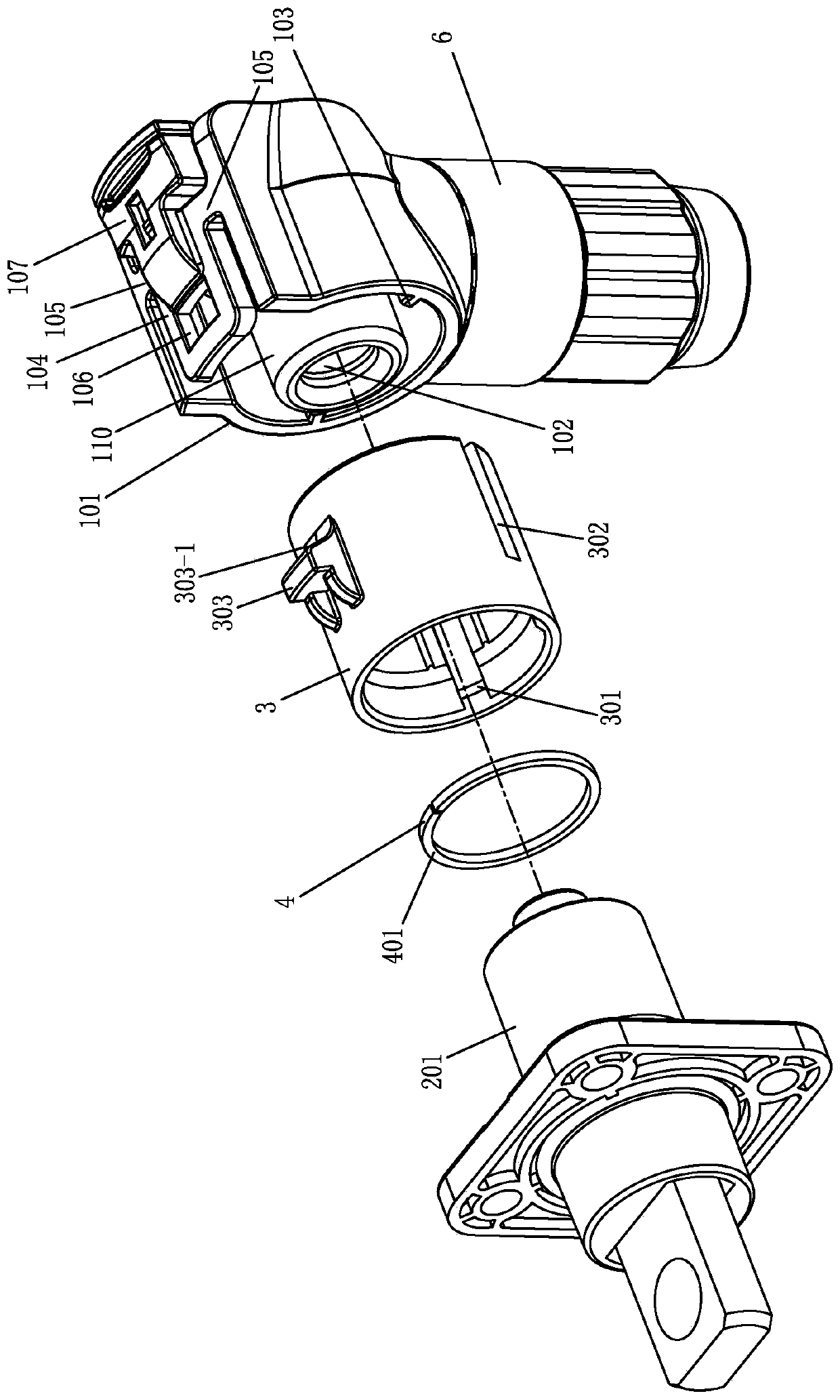
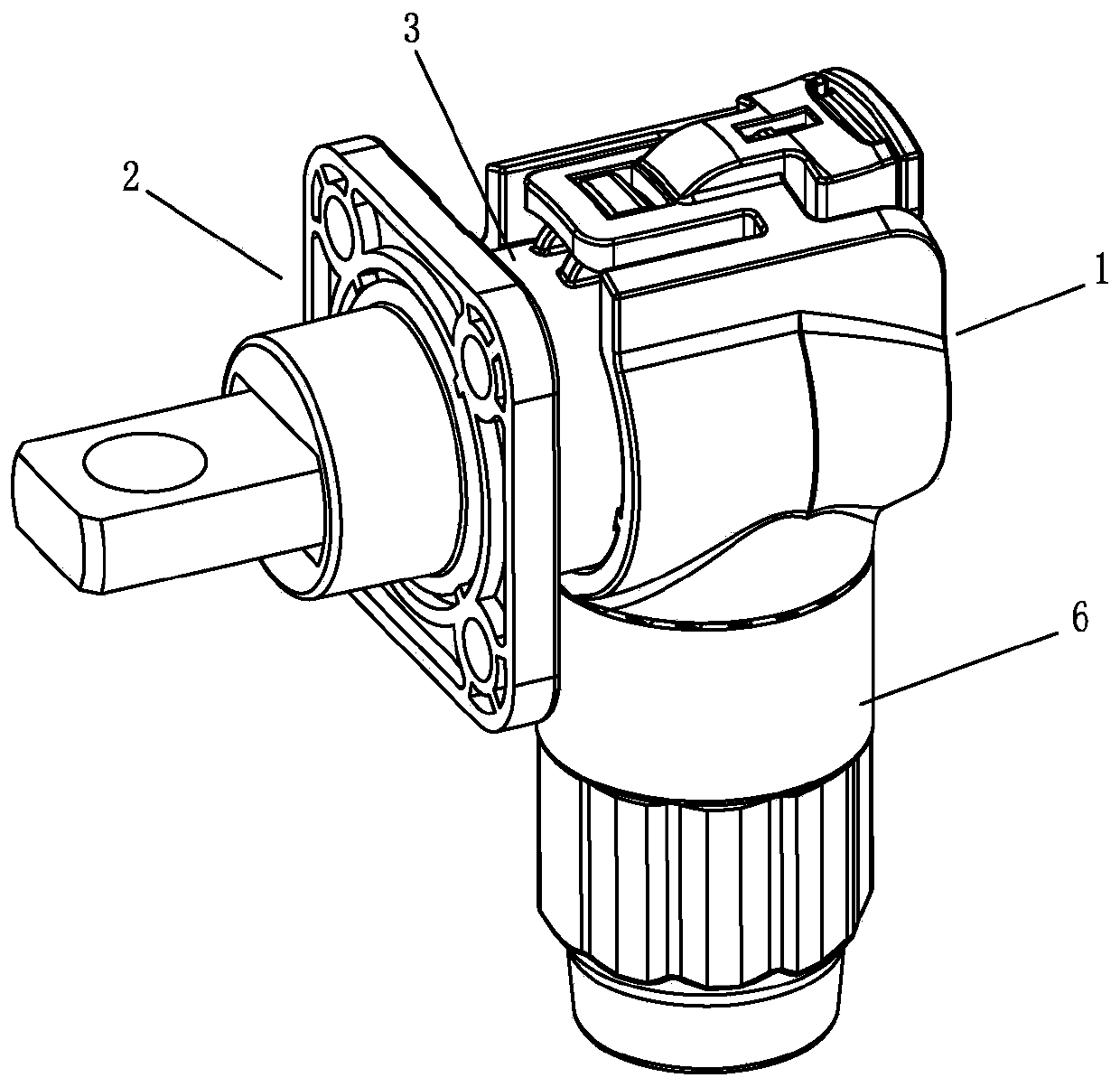
[0024] Such as Figure 1-Figure 7 As shown: a rotatable electrical connector, including a plug 1 and a socket 2, the socket 2 is provided with a hollow socket column 201, the socket column 201 is connected with a socket metal terminal 202, and the outer peripheral wall of the socket column 201 is rotated. Connected with the rotating sleeve 3, the plug 1 is provided with a plug column 101, and the plug column 101 is connected with a plug metal terminal 102. It is characterized in that a groove 203 is opened on the outer peripheral wall of the socket column 201 according to the circumferential direction, and the groove 203 A retaining ring 4 is arranged on the top, and the inner wall of the rotating sleeve 3 extends to limit the protrusion 301 , the rotating sleeve 3 is rotatably socketed on the socket column 201 , and the limiting protrusion 301 is fastened to the ...


PUM


Abstract

The utility model discloses a rotatable electric connector. The connector comprises a plug and a socket, wherein a hollow socket column is arranged on the socket, and a socket metal terminal is connected in the socket column. The outer circumferential wall of the socket column is rotationally sleeved with a rotating sleeve, a plug column is arranged in the plug, and a plug metal terminal is connected in the plug column. A groove is formed in the outer circumferential wall of the socket column in the circumferential direction, and a check ring is arranged on the groove. The inner wall of the rotating sleeve extends to form a limiting protruding block, and the rotating sleeve is rotationally connected to the socket column in a sleeving mode. The limiting protruding block is connected to theinner side of the check ring in a buckled mode. The check ring is arranged to be an independent part, and the check ring is preferably made of a metal material, so the structure of the check ring is more wear-resistant, and the structural strength is higher. Moreover, after the check ring is in contact with the limiting convex block in the groove, when the rotating sleeve rotates, the effect of increasing the damping feeling is achieved, so that the using effect is better.

Description

technical field [0001] The invention relates to the technical field of electrical connectors, in particular to a rotatable electrical connector. Background technique [0002] At present, with the advancement of new energy technology, the types of electrical connectors are also improved. For example, the technical solution of Chinese patent ZL201510390015.8 discloses an electrical connector that can realize high-voltage connection and conduction, and can be rotated at any angle. , wherein the clamping convex ring 1-112 on the socket column 1-11 and the clamping groove of the rotatable body 1-2 cooperate with each other to realize the rotation of the rotatable body 1-2, and the clamping convex ring 1-112 is integrated It is set on the socket column 1-11 made of plastic material, and the clamping groove is set on the rotatable body 1-2 made of plastic material as a whole. The structure made of plastic material has low strength and poor wear resistance, and it is easy to appear ...

Claims


Application Information

Patent Timeline
IPC IPC(8): H01R13/502H01R13/627H01R24/00H01R35/04
CPCH01R13/502H01R13/627H01R24/005H01R35/04
Inventor 邵土贤曾晨波
Owner 广州亿威科技有限责任公司
Features
  • R&D
  • Intellectual Property
  • Life Sciences
  • Materials
  • Tech Scout
  • Unparalleled Data Quality
  • Higher Quality Content
  • 60% Fewer Hallucinations
Learn More