Computer hardware monitoring device

A computer hardware and monitoring device technology, applied in the field of computer hardware monitoring devices, can solve problems such as difficult recovery and preservation, computer hardware burnout, single detection range, etc., and achieve the effect of compact structure design, obvious wear and dust, and accurate positioning monitoring

Active Publication Date: 2019-08-27
ANYANG NORMAL UNIV
View PDF7 Cites 0 Cited by
  • Summary
  • Abstract
  • Description
  • Claims
  • Application Information

AI Technical Summary

Problems solved by technology

[0002]With the development of science and the progress of society, modern equipment gradually appears in our life. Modern equipment not only provides convenience to our life, but also modern Equipment also promotes the progress of our society. As the most common equipment in people's daily life, computers are widely used in all aspects of life. Due to improper protection of people, when computers are in use, the hard hardware of the computer is easy to heat up, making Computer hardware is easy to be burned, and there is no early warning device that can remind users of the real-time operating temperature of computer hardware, which brings great inconvenience to users
[0003] In order to solve the above problems, the present invention is proposed, which overcomes the current use of computer hardware monitoring equipment, the electronic monitoring components are welded in the detection device, resulting in a single detection range, Moreover, it is difficult to replace the monitoring items, the combination adjustment is cumbersome, and even effective monitoring and detection cannot be carried out, which makes the monitoring process take a long time and the effect is poor. It solves the problem that the currently used computer hardware monitoring equipment cannot adjust the monitoring parts well and accurately, resulting in accurate monitoring. In addition, components are often not disassembled after use, are difficult to recycle and store, wear and fall dust is obvious, and are easy to be damaged, so that the present invention has the advantages of compact structure design, fast installation and disassembly, accurate positioning and monitoring, various functions and collocations, and simple storage.

Method used


Image

  • Computer hardware monitoring device
  • Computer hardware monitoring device
  • Computer hardware monitoring device

Examples


Embodiment Construction

[0018] The following will clearly and completely describe the technical solutions in the embodiments of the present invention with reference to the accompanying drawings in the embodiments of the present invention. Obviously, the described embodiments are only some, not all, embodiments of the present invention. Based on the embodiments of the present invention, all other embodiments obtained by persons of ordinary skill in the art without making creative efforts belong to the protection scope of the present invention.

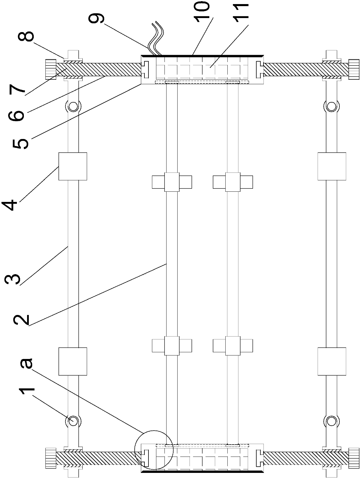
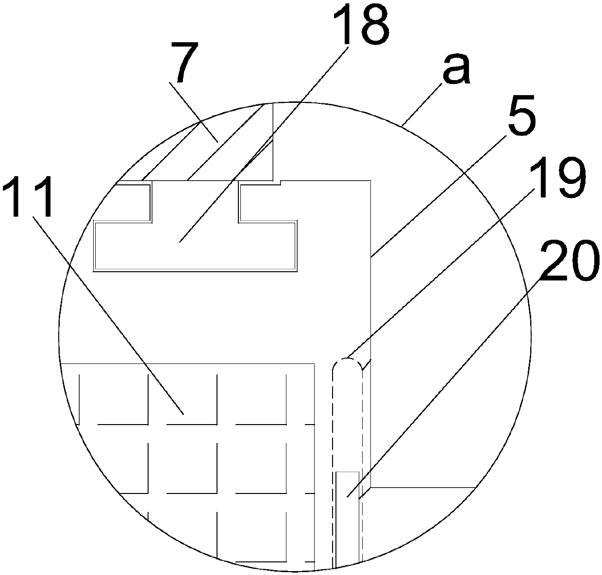
[0019] see Figure 1~4 , in an embodiment of the present invention, a computer hardware monitoring device includes left and right symmetrical support installation plates 5, two sets of translation installation columns 2 are arranged in parallel between the support installation plates 5 on the left and right sides. The left and right ends of the moving installation column 2 cooperate with the support installation plate 5 to be symmetrically provided with guide ...


PUM


Abstract

The invention discloses a computer hardware monitoring device. The device comprises supporting mounting plates symmetrically arranged left and right; two groups of translation mounting columns arranged between the supporting mounting plates on the left side and the right side in parallel; and limiting telescopic studs symmetrically arranged on the front side and the rear side of the supporting mounting plate. The limiting telescopic studs on the same side are matched with each other and are horizontally provided with movable mounting columns. Telescopic mounting screw cylinders are embedded inthe movable mounting columns and matched with the limiting telescopic studs. Linkage rotating shafts matched with the limiting telescopic studs are symmetrically arranged at the two ends of the movable mounting column. Sliding detection structures are symmetrically arranged on the movable mounting column between the linkage rotating shafts; and sliding detection structures are also symmetricallyarranged on the translation mounting columns and comprise semicircular mounting frames movably arranged through rotating shafts. The device has the advantages of being compact in structural design, quick to mount and dismount, accurate in positioning and monitoring, diverse in function matching, simple to store and the like.

Description

technical field [0001] The invention relates to a monitoring device, in particular to a computer hardware monitoring device. Background technique [0002] With the development of science and the progress of society, modern equipment gradually appears in our life. Modern equipment not only provides convenience to our life, but also promotes the progress of our society. The most common equipment is widely used in all aspects of life. Due to improper protection of people, when the computer is in use, the hard hardware of the computer is easy to get hot, which makes the computer hardware easy to be burned, and there is no early warning device that can prompt the use Or the real-time working temperature of the computer hardware, which brings great inconvenience to the user. [0003] In order to solve the above problems, the present invention is proposed, which overcomes the currently used computer hardware monitoring equipment, and the electronic monitoring components are welded...

Claims


Application Information

Patent Timeline
Patent Type & Authority Applications(China)
IPC IPC(8): G06F11/30
CPCG06F11/3058
Inventor 马辉李娜史小松杨孝敬刘运通
Owner ANYANG NORMAL UNIV
Why Eureka
Try Eureka