
A driving signal timing method for hybrid clamped three-level h-bridge inverter

A driving signal, hybrid clamping technology, applied in electrical components, output power conversion devices, AC power input conversion to DC power output and other directions, can solve problems such as reduced equipment reliability, complex control algorithms, and complex voltage equalization methods. , to solve the pressure equalization problem, achieve simple, easy to understand and use effects

Active Publication Date: 2020-12-08
达微智能科技(厦门)有限公司
View PDF5 Cites 0 Cited by
  • Summary
  • Abstract
  • Description
  • Claims
  • Application Information

AI Technical Summary

Problems solved by technology

This kind of method will lead to very complex control algorithm, thus increasing the difficulty of control
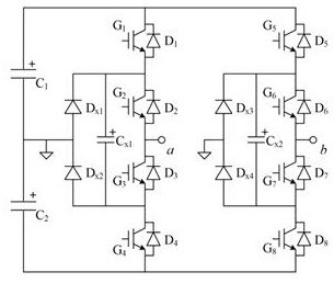
The second type of method is to use flying capacitors (such as figure 1 C in x1 、C x2 ), to make it participate in the charging and discharging process of the bus capacitor, so as to realize the voltage equalization of the bus capacitor. This kind of method will have higher requirements on the capacity of the flying capacitor, which will reduce the reliability of the equipment
The above bus capacitor voltage equalization methods for hybrid clamped three-level inverters are too complicated and not very practical

Method used


Image

  • A driving signal timing method for hybrid clamped three-level h-bridge inverter
  • A driving signal timing method for hybrid clamped three-level h-bridge inverter
  • A driving signal timing method for hybrid clamped three-level h-bridge inverter

Examples


Embodiment Construction

[0024] In order to enable those skilled in the art to better understand the solutions of the present invention, the following will clearly and completely describe the technical solutions in the embodiments of the present invention in conjunction with the drawings in the embodiments of the present invention. Obviously, the described embodiments are only It is an embodiment of a part of the present invention, but not all embodiments. Based on the embodiments of the present invention, all other embodiments obtained by persons of ordinary skill in the art without creative efforts shall fall within the protection scope of the present invention.

[0025] It should be noted that the terms "first" and "second" in the description and claims of the present invention and the above drawings are used to distinguish similar objects, but not necessarily used to describe a specific sequence or sequence.

[0026] An embodiment of the present invention provides a driving signal timing method fo...


PUM


Abstract

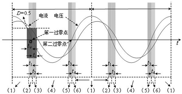
The invention relates to a driving signal timing method of a hybrid clamping type three-level H-bridge inverter. The inverter comprises two bus capacitor banks; the two bus capacitor banks are connected in series; in a driving signal timing process, the inverter is used for outputting pulse width modulation waves; in each modulation wave period, only one bus capacitor bank of the inverter is connected to a load for charging and discharging in a plurality of carrier periods near an output voltage zero crossing point; a charging time and a discharging moment of the same bus capacitor bank are symmetric relative to the zero crossing point on a time axis; a zero crossing point of an output voltage falling section is a first zero crossing point; a zero crossing point of a voltage rising sectionis a second zero crossing point; the moment when the first bus capacitor bank is connected to the load for charging and discharging, and the moment when the second bus capacitor bank is connected tothe load for charging and discharging are located at the first zero crossing point and the second zero crossing point respectively or vice versa; and the total time for the first bus capacitor bank tobe independently connected to the load for charging and discharging is equal to the total time for the second bus capacitor bank to be independently connected to the load for charging and discharging.

Description

technical field [0001] The invention relates to a driving signal timing method of an H-bridge inverter, in particular to a driving signal timing method of a hybrid clamp type three-level H-bridge inverter, and relates to the technical field of power electronic converters. Background technique [0002] The three-level inverter has the characteristics of low voltage stress of the switching tube and small filter, and is currently widely used in power converters, motor drives and other occasions. According to different topological structures, three-level inverters are mainly divided into three types: diode-clamped, flying-capacitor-clamped, and hybrid-clamped. Among them, the hybrid clamp type three-level inverter combines the advantages of the diode clamp type and the flying capacitor clamp type, which can well solve the voltage stress problem of all switching tubes in the inverter, and has a high reliability. [0003] figure 1 is the topology of hybrid clamped three-level H...

Claims


Application Information

Patent Timeline
Patent Type & Authority Patents(China)
IPC IPC(8): H02M7/487H02M7/5387
CPCH02M7/487H02M7/5387
Inventor 蔡卓剑
Owner 达微智能科技(厦门)有限公司
Learn More