
Wafer box electronic label power alarm device

A technology of electronic tags and alarm devices, which is applied in the field of wafer box electronic tag power alarm devices, can solve problems such as mishandling products, delaying product processing time, and inability to interact with information in semiconductor manufacturing systems, so as to ensure timely updates and improve production efficiency. and quality, to ensure the effect of normal operation

Active Publication Date: 2021-04-20
ZHENGZHOU UNIV OF IND TECH
View PDF12 Cites 0 Cited by
  • Summary
  • Abstract
  • Description
  • Claims
  • Application Information

AI Technical Summary

Problems solved by technology

When the battery power is exhausted, the electronic label cannot work normally and cannot exchange information with the semiconductor manufacturing system, so the product information in the wafer cassette cannot be updated
[0005] The current practice is that the operator replaces the battery only when the electronic label is out of power. This not only delays the product processing time, but also causes mishandling of the product because the product information parameters are not updated in time and cannot effectively identify the product information.

Method used


Image

  • Wafer box electronic label power alarm device
  • Wafer box electronic label power alarm device
  • Wafer box electronic label power alarm device

Examples


Embodiment Construction

[0019] In order to make the purpose, features and effects of the present invention more obvious and understandable, the specific implementation manners of the present invention will be described in detail below in conjunction with the accompanying drawings.

[0020] Many specific details are set forth in the following description to facilitate a full understanding of the present invention, but the present invention can also be implemented in other ways than described here, so the present invention is not limited by the specific embodiments disclosed below.

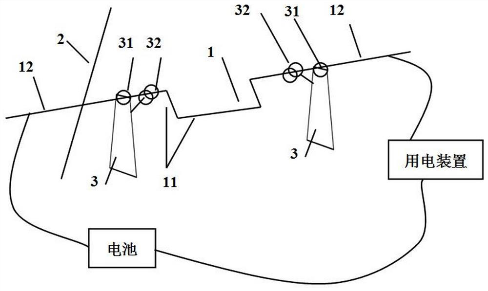
[0021] The force on the current-carrying wire in the magnetic field, the size of the Ampere force is related to the magnetic induction intensity, the current in the conductor, the length of the conductor, and the angle between the current and the direction of the magnetic field. In a uniform magnetic field, the relationship between them is as follows figure 1 As shown, the meaning of each parameter is as follows:

[0022] ...


PUM


Abstract

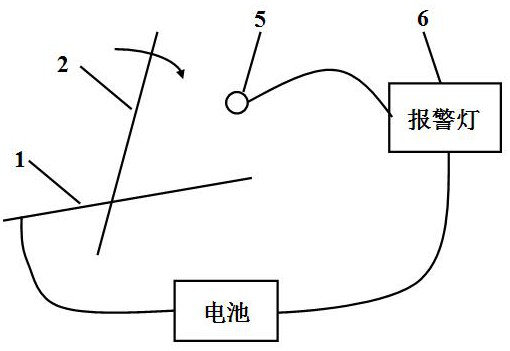
The invention relates to an electric quantity alarm device for a wafer box electronic label. The electricity alarm device includes: a U-shaped rod with rigid conductivity, a connecting rod with rigid conductivity, a bracket, a permanent magnet providing a uniformly distributed magnetic field, conductive contact points, and a warning light. The invention can better monitor the power of the wafer box electronic label battery.

Description

technical field [0001] The invention relates to the field of semiconductors, in particular to an electric quantity alarm device for a wafer cassette electronic label. Background technique [0002] With the development of semiconductor technology, semiconductor companies will use software control systems to maximize the production capacity of semiconductor production equipment. The core of this series of control systems is the Manufacturing Execution System (MES). The MES system has a powerful data collection engine, and the data collection channels cover the entire factory manufacturing site, ensuring real-time, accurate and comprehensive collection of on-site data, which records data such as product information parameters and equipment information parameters. [0003] From production to transportation, wafers need to be carried out under airtight and dust-free conditions, and wafers are loaded in wafer boxes to complete various manufacturing processes. Wafers enter and exi...

Claims


Application Information

Patent Timeline
Patent Type & Authority Patents(China)
IPC IPC(8): G01R31/382G06K19/077
CPCG06K19/07701G01R31/382
Inventor 欧阳富王君莉
Owner ZHENGZHOU UNIV OF IND TECH
Learn More