A release coil disconnection monitoring circuit

A technology for monitoring circuits and releases, which is applied in the direction of electrical winding testing, continuity testing, and switchgear status indication. It can solve problems such as high power consumption of the MCU, large standby current, and coil malfunctions, thereby reducing development investment, Enhanced reliability and prevent malfunction

Active Publication Date: 2021-01-12
XIAMEN LEELEN ELECTRICAL CONTROL TECH CO LTD
View PDF6 Cites 0 Cited by
  • Summary
  • Abstract
  • Description
  • Claims
  • Application Information

AI Technical Summary

Problems solved by technology

[0005] However, the MCU solution has poor versatility and cannot be used universally for single-coil releases and double-coil releases; and due to the introduction of MCU, the overall requirements for the system (such as EMC, etc.) are relatively high, and the development and design investment is relatively high.
At the same time, due to the relatively high power consumption of the MCU, the standby current is large; due to the current low power consumption requirements, the comprehensive protection device used in conjunction with the coil monitoring function has smaller requirements for the standby current. If the standby current is too large, it is easy to Misjudging the disconnection of the coil as the coil is normal, resulting in misjudgment; in addition, the monitoring current directly passes through the working coil, which may cause the risk of coil malfunction

Method used


Image

  • A release coil disconnection monitoring circuit
  • A release coil disconnection monitoring circuit
  • A release coil disconnection monitoring circuit

Examples


Embodiment Construction

[0023] The technical solutions in the embodiments of the present invention will be clearly and completely described below with reference to the accompanying drawings in the embodiments of the present invention. Obviously, the described embodiments are only a part of the embodiments of the present invention, but not all of the embodiments. Based on the embodiments of the present invention, all other embodiments obtained by those of ordinary skill in the art without creative efforts shall fall within the protection scope of the present invention.

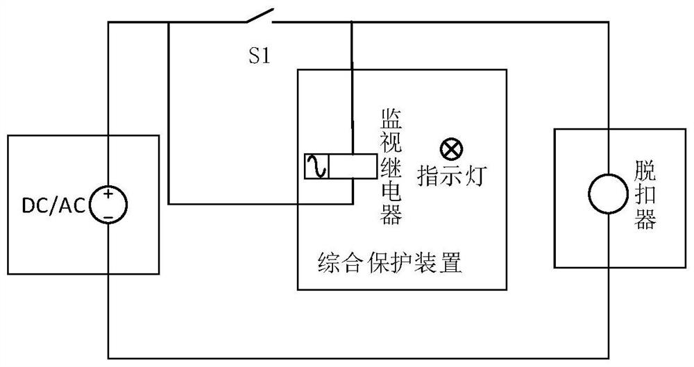
[0024] refer to figure 1 , a release coil disconnection monitoring circuit, including a comprehensive protection device, a release, a switch S1 and a power supply, the release is connected to the power supply after being connected in series with the comprehensive protection device, and the switch S1 and The comprehensive protection device is connected in parallel;

[0025] The release includes a release coil monitoring module, a rele...


PUM


Abstract

The present invention is a coil disconnection monitoring circuit of a tripper. By adding a circuit in the tripper, the coil monitoring scheme is realized by means of a hardware circuit; it satisfies the two working principles of "single coil" and "double coil". Application of the trip unit; there is no change in the "incentive" - ​​"hold" working process of the trip unit itself, with good versatility and scalability. Including comprehensive protection device, trip unit, switch S1 and power supply, the trip unit is connected to the power supply after being connected in series with the comprehensive protection device, and the switch S1 is connected in parallel with the comprehensive protection device; the trip unit includes a release coil monitoring module, a release coil Module and release coil control module M1; the input terminal of the release coil control module M1 is connected to the power supply, and the output terminal is connected to the release coil module to control the conduction or closure of the release; the release coil The monitoring module monitors the on-off of the release coil module, and outputs the monitoring results through the comprehensive protection device.

Description

technical field [0001] The invention relates to the field of trip coil monitoring, in particular to a trip coil disconnection monitoring circuit. Background technique [0002] The shunt / closing release of the power circuit breaker works instantaneously, and it only works when it is powered on, and it is in a non-working state without power at other times. The power circuit breaker has very high requirements on reliability. If the release cannot be closed or opened normally, serious consequences will be caused, resulting in significant economic losses. Therefore, in the design of the control cabinet, it is required that the circuit breaker product itself has a monitoring function to monitor whether the internal coil of the release is disconnected or not. [0003] According to the number of internal coils, the release can be divided into two schemes: "single coil" and "double coil". The "single coil" scheme has two working modes, one is to disconnect the current of the coil ...

Claims


Application Information

Patent Timeline
Patent Type & Authority Patents(China)
IPC IPC(8): H01H71/04G01R31/54G01R31/72
CPCH01H71/04G01R31/72G01R31/50
Inventor 颜自勇翁金彬柯成杰
Owner XIAMEN LEELEN ELECTRICAL CONTROL TECH CO LTD
Why Eureka
Try Eureka