Spinal Radius Adjustment Device
A technology for adjusting devices and radians, which is applied in roller massage, passive exercise equipment, medical science, etc., and can solve problems such as long treatment courses, costly illnesses, and difficult non-surgical treatments
- Summary
- Abstract
- Description
- Claims
- Application Information
AI Technical Summary
Problems solved by technology
Method used
Image
Examples
Embodiment 1
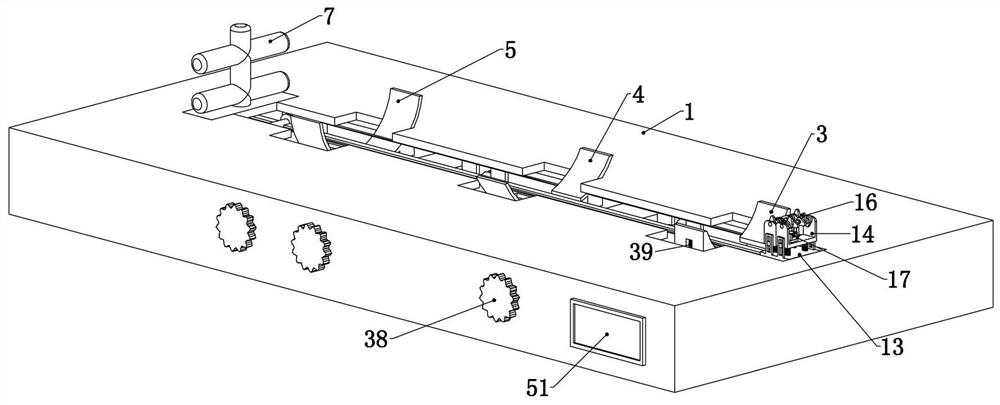
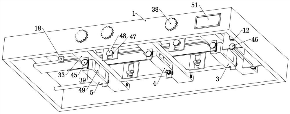
[0037] Embodiment 1, the present invention is a spinal radian adjustment device, including a base 1, the base 1 is a hollow bottomless cubic shell, which is used to provide a fixed foundation for subsequent structures, and the user can also start using the device When laying on the base 1 first, it is characterized in that three support plates 2 are connected horizontally side by side up and down on the base 1, and the three support plates 2 are called cervical spine support plates from right to left. 3. Thoracic support plate 4, lumbar support plate 5, refer to figure 2 , Figure 4, the three supporting plates 2 are all circular arc plates, which are used to fit the corresponding body parts, and their edges should be smooth and polished to prevent the edges and corners from causing harm to the user. The three supporting plates 2 are respectively used to support the user's cervical spine , thoracic vertebrae and lumbar vertebrae, the central angle of which is different due t...
Embodiment 2
[0040] Embodiment 2. On the basis of Embodiment 1, this embodiment provides a specific massage device on the massage trolley 8, so as to have a better relaxing massage effect on the user's spine and the muscles around the spine. Specifically, the The massage trolley 8 includes a trolley base 13 slidingly connected to the base 1 left and right, two sets of walking wheels are rotatably connected to the trolley base 13, and a trolley is fixedly connected to the base 1. Walking track, two sets of walking wheels can roll on the trolley track and drive the trolley base 13 to walk on the trolley track. The trolley base 13 is connected with two trolley support seats 14 side by side and slide up and down. Camshafts 15 are rotatably connected to the two trolley support seats 14, and several cams 16 are evenly and fixedly connected to the two camshafts 15, and the two camshafts 15 are fixedly connected to the support seats. The trolley motors 17 are connected, specifically, the output sh...
Embodiment 3
[0041] Embodiment 3. On the basis of Embodiment 1, this embodiment provides a specific structure of a wire wheel set. The wire wheel set includes a wire wheel driven wheel 18 and a wire wheel driven wheel 18 connected in rotation to the left end of the base 1. Rotate the wire wheel driving wheel 19 connected to the right end of the base 1, the wire wheel driving wheel 19 is connected with the wire wheel main gear 9, so that the wire wheel main gear 9 drives the wire wheel driving gear 22 to rotate , the wire pulley drive wheel 19 is coaxially fixedly connected with a wire pulley drive pulley 21, and the wire pulley driven pulley 18 is coaxially fixedly connected with a wire pulley driven pulley 20, and the wire pulley driven pulley 20 and the wire pulley The driving pulleys 21 are connected by belts. The wire wheel driving pulley 19 and the wire wheel driven pulley 18 are wound with a rope whose other end is fixedly connected to the massage trolley 8. The wire wheel driving pul...
PUM
 Abstract
Description
Claims
Application Information
 - R&D
- Intellectual Property
- Life Sciences
- Materials
- Tech Scout
- Unparalleled Data Quality
- Higher Quality Content
- 60% Fewer Hallucinations
Browse by: Latest US Patents, China's latest patents, Technical Efficacy Thesaurus, Application Domain, Technology Topic, Popular Technical Reports.
© 2025 PatSnap. All rights reserved.Legal|Privacy policy|Modern Slavery Act Transparency Statement|Sitemap|About US| Contact US: help@patsnap.com


