Supercharge Your Innovation With Domain-Expert AI Agents!

Stop type door closer

A door closer and fixed type technology, applied in the field of stop-type door closers, can solve the problems of not being able to close the door at any time, unable to maintain the open position of the door, etc., to achieve the effect of increasing the closing trend, closing the door easily, and releasing the door easily

Pending Publication Date: 2019-09-06
SUZHOU FUERDA TECH CO LTD
View PDF2 Cites 0 Cited by
  • Summary
  • Abstract
  • Description
  • Claims
  • Application Information

AI Technical Summary

Problems solved by technology

[0004] The Chinese patent document whose publication number is "CN 102191899 A" discloses a "door closer", which Figure 2 to Figure 5 The embodiment shown can stop the door in any open position and close the door after a delay, but it has disadvantages: it cannot keep the door in the open position for a long time, and it cannot close the door at any time
[0005] The Chinese patent document whose publication number is "CN 87 2 14794 U" discloses a "delayed automatic door closer with positioning function", which can stop the door at a relatively large angle and can stop for a long time, but its Disadvantages: the door can only be released by closing the door manually

Method used


Image

  • Stop type door closer
  • Stop type door closer
  • Stop type door closer

Examples


Embodiment 1

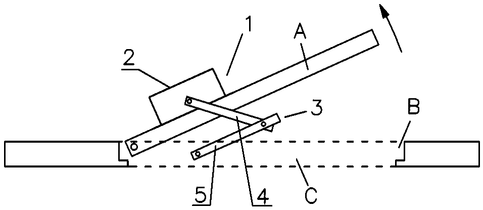
[0108] Such as figure 1 , The door closer 1 is installed on the door A and the door frame C, the door A is set at the opening B of the door frame and is hinged with the side of the door frame C. The main shell 2 of the door closer 1 is installed on the door A, and the coupling mechanism 3 is connected to the upper lintel of the door frame C. The coupling mechanism 3 includes a first arm 4 and a second arm 5 . One end of the second arm 5 is hinged with the upper lintel of the door frame C, the other end of the second arm 5 is hinged with one end of the first arm 4 , and the other end of the first arm 4 is hinged with the main shell 2 .

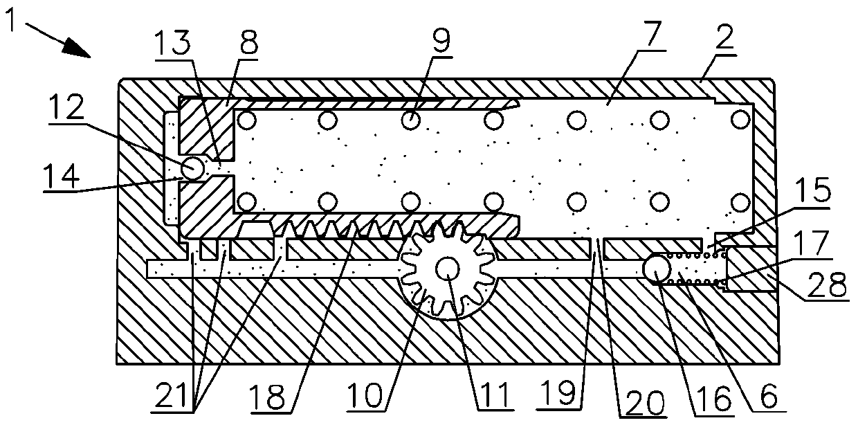
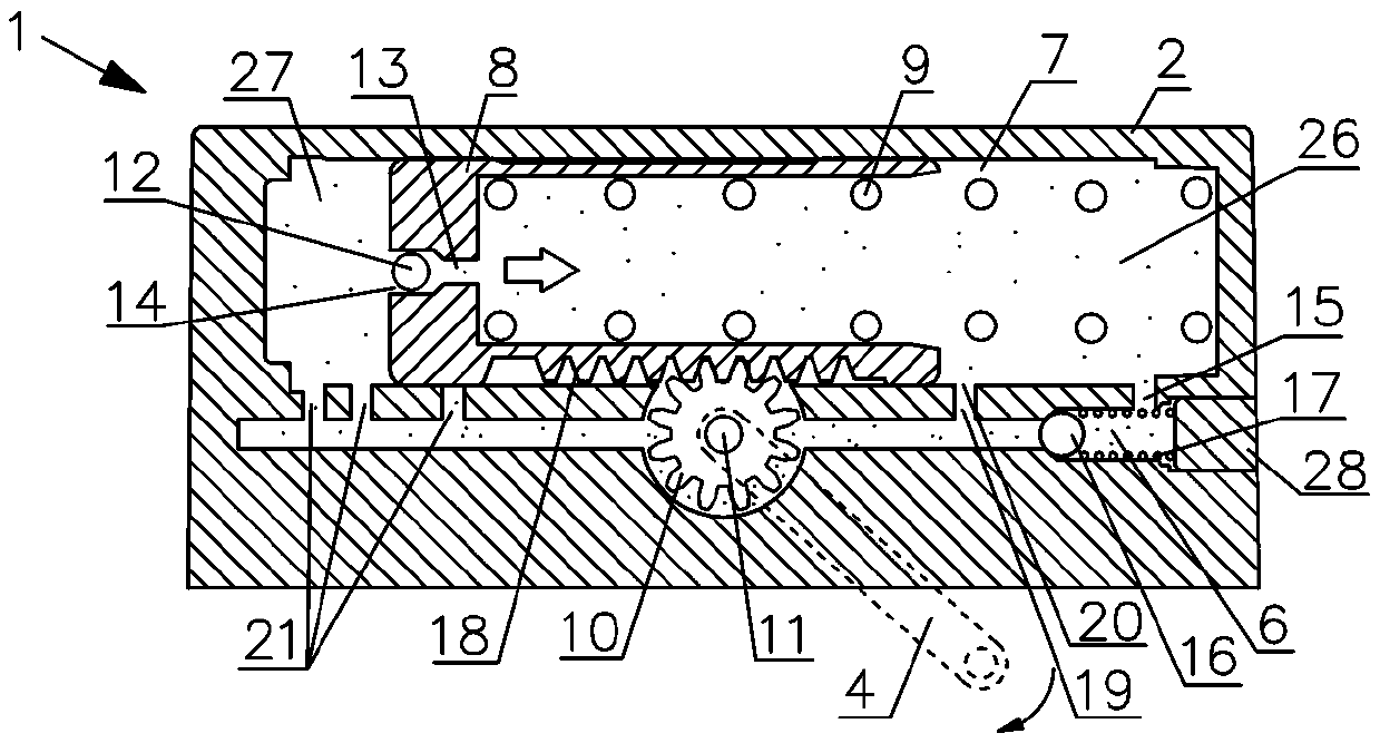
[0109] Such as figure 2 , in fact, the other end of the first arm 4 is fixed on the gear shaft 11 .

[0110] Such as figure 2 , The door closer 1 includes a main shell 2, the main shell 2 is provided with an inner chamber 7, and the piston 8 is slidably arranged in the inner chamber 7. The inner cavity 7 is filled with fluid, which is h...

Embodiment 2

[0131] Such as Figure 7 In the shown embodiment 2, a release unit 22 is added on the basis of the embodiment 1, and the same parts as the embodiment 1 are marked with the same reference numerals. The release unit 22 is used to release the closing valve 16 .

[0132] The release unit 22 includes a push rod 23 and a power element for pushing the push rod 23 , that is, a conductive coil 24 . The push rod 23 is magnetic and is arranged in the conductive coil 24 . When the conductive coil 24 is energized, the magnetic field generated by the conductive coil 24 acts on the push rod 23 to push the push rod 23 forward to squeeze the small spring 17 so as to apply a continuous pressing force to the closing valve 16 . At this time, the effect of the door closer is the same as in Embodiment 1.

[0133] Such as Figure 8 , when the conductive coil 24 is powered off, the magnetic field of the conductive coil 24 is released, and the push rod 23 releases the pressing force on the closing...

Embodiment 3

[0137] Such as Figure 9 In the shown embodiment 3, the release unit 22 is also provided, and the same parts as in the embodiment 1 are marked with the same reference numerals. Different from Embodiment 2, the release unit 22 does not directly act on the closing valve 16 , but acts on the added fourth flow path 25 , and the added fourth flow path 25 cooperates with the release unit 22 .

[0138] The fourth flow path 25 is arranged in the main casing 2 and connects the front and rear inner chambers 7 in the traveling direction of the piston 8 . The release unit 22 includes a push rod 23 and a power element for pushing the push rod 23 , that is, a conductive coil 24 . The push rod 23 is magnetic and is arranged in the conductive coil 24 . When the conductive coil 24 is energized, the magnetic field generated by the conductive coil 24 acts on the push rod 23 to advance the push rod 23 into the fourth flow path 25 and block the fourth flow path 25 . At this time, the effect of ...


PUM


Abstract

The invention relates to a stop type door closer, which includes a main shell, a piston, a main spring, a first fluid passage, a second fluid passage and a removing unit. An inner cavity is formed inthe main shell, the piston is arranged in the inner cavity and connected to a connecting mechanism linked with opening and closing of a door, the main spring accumulates door closing energy through piston movement when the door is opened, a one-way valve is arranged in the first fluid passage and used for controlling fluid on the front side in the direction of piston movement to flow to the rear side of the direction of piston movement, a door closing valve is arranged in the second fluid passage, the second fluid passage is used for allowing the front side and the rear side of the direction of piston movement to communicate, when the door stops at any opening position within a set range of movement, the fluid pressure difference between the front side and the rear side of the direction ofpiston movement is maintained to maintain the stop state of the piston, and the differential pressure in the fluid is used for releasing the door closing valve; and the removing unit is used for removing the action of the second fluid passage, and the time of removing the stop state of the door is not limited, and is not limited to manpower door closing trigger removing.

Description

technical field [0001] The invention relates to a door closer, in particular to a stationary door closer. Background technique [0002] In the windows or doors of residential buildings, apartments, commercial buildings and other buildings, door closers are sometimes required. The door closers have springs for energy storage. When the door is opened, the springs accumulate energy; after the external force is released, the springs release the accumulated energy. The purpose of automatic door closing. [0003] In reality, there is a need for a door closer that can stop the door and maintain the open state after the door is opened, and needs to release the open state to close the door. [0004] The Chinese patent document whose publication number is "CN 102191899 A" discloses a "door closer", which Figure 2 to Figure 5 The shown embodiment is capable of stopping the door in any open position and closing the door after a time delay, but it has the disadvantage that it cannot ma...

Claims


Application Information

Patent Timeline
IPC IPC(8): E05F3/10E05F3/22
CPCE05F3/10E05F3/22
Inventor 朱力克聂飞
Owner SUZHOU FUERDA TECH CO LTD
Features
  • R&D
  • Intellectual Property
  • Life Sciences
  • Materials
  • Tech Scout
  • Unparalleled Data Quality
  • Higher Quality Content
  • 60% Fewer Hallucinations
Learn More