Supercharge Your Innovation With Domain-Expert AI Agents!

Ventilation equipment

A technology of ventilation equipment and ventilation grids, which is applied in mechanical equipment, electrical equipment structural parts, cooling/ventilation/heating transformation, etc., to save time and save maintenance.

Active Publication Date: 2015-11-25
RITTALWERK RUDOLF LOH GMBH & CO KG
View PDF3 Cites 0 Cited by
  • Summary
  • Abstract
  • Description
  • Claims
  • Application Information

AI Technical Summary

Problems solved by technology

This filter mat must be replaced regularly

Method used


Image

  • Ventilation equipment
  • Ventilation equipment
  • Ventilation equipment

Examples


Embodiment Construction

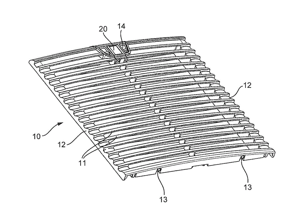
[0019] figure 1 A ventilation grid 10 is shown with a plurality of mutually parallel vanes 11 . The ends of the blades 11 on their longitudinal sides are integrally connected to each other by connecting pieces 12 . In the region of the horizontal lower edge, the ventilation grid 10 has two hinge receivers 13 which are provided to form a horizontal hinge axis. The ventilation grid 10 is edged horizontally with cover receivers 14 . A handle 20 is fastened in this cover receiver 14 .

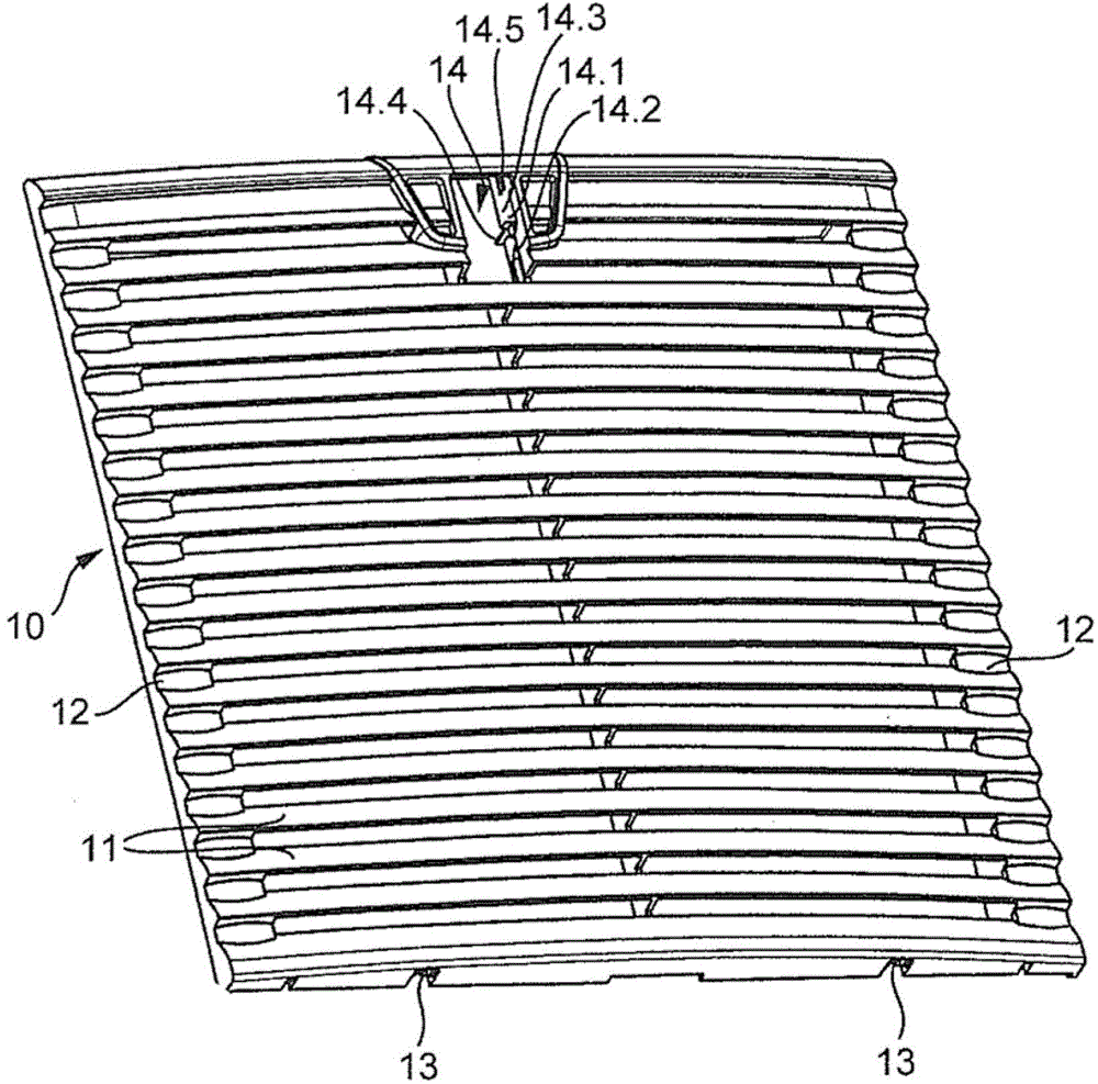
[0020] figure 2 shows the basis figure 1 The ventilation grid 10, but the handle 20 is removed. As can be seen from this illustration, the ventilation grid 10 is provided with openings in the region of the cover receiver 14 . Here, the recess is delimited laterally by two parallel guide walls 14.3. A recess is machined into the guide wall 14.3, which recess forms the bearing receptacle 14.1. The bearing receiver 14.1 has a guide part in which snap-fit ​​elements 14.4 are integrated. Furth...


PUM


Abstract

The invention relates to an air guidance system having an air guidance housing and an air passage grating fastened thereto, the air passage grating being held on the air guidance housing by means of a snap-lock connection. In order to simplify maintenance of such an air guidance system it is provided according to the invention that the air passage grating carries at least one latch having a snap-in shoulder that can be engaged in a snap-lock seat of the air passage grating and that the air passage grating pivotally accommodates a handle in a bearing seat, said handle disengaging the latch from the snap-lock seat when set from the locking position to the unlocking position.

Description

technical field [0001] The invention relates to a ventilation device with a ventilation housing and a ventilation grid fastened thereto, wherein the ventilation grid is held on the ventilation housing by a snap connection. Background technique [0002] Such ventilation devices are used in switch cabinets and can be inserted into a part of the switch cabinet wall. Usually, a ventilator assembly is combined with the ventilating device, which draws in ambient air through the ventilating grid and discharges the ambient air via the ventilating housing into the switchgear interior. [0003] A filter mat, which filters particles from the sucked-in air, is usually held within the ventilated housing. This filter mat must be replaced periodically. To do this, remove the ventilation grid from the ventilation housing. The ventilation grid is held on the ventilation housing by a snap connection. Here, the snap connection is designed such that it can only be unlocked with a screwdrive...

Claims


Application Information

Patent Timeline
Patent Type & Authority Patents(China)
IPC IPC(8): H05K7/20
CPCH05K7/20181F04D29/646F04D29/703H05K5/0221H05K7/20418H05K7/20472
Inventor R.哈特曼S.施耐德C.C.龙泽默
Owner RITTALWERK RUDOLF LOH GMBH & CO KG
Features
  • R&D
  • Intellectual Property
  • Life Sciences
  • Materials
  • Tech Scout
  • Unparalleled Data Quality
  • Higher Quality Content
  • 60% Fewer Hallucinations
Learn More