Method for detecting image flicker stripes and method for adjusting image exposure time

A technology for detecting images and images, which is applied in image communication, color TV parts, TV system parts, etc., can solve the problems of large motion influence, high computational complexity, low flicker detection accuracy and detection rate, etc. , to achieve the effect of reducing computational complexity and good application value

Active Publication Date: 2019-09-06
CHENGDU LIGHT COLLECTOR TECH
View PDF9 Cites 8 Cited by
  • Summary
  • Abstract
  • Description
  • Claims
  • Application Information

AI Technical Summary

Benefits of technology

This technology helps analyze captured video data from cameras or other devices without having them move around during capturing time. It uses an analysis process called histogramming to determine how long each pixel was exposed before being counted down into different colors. By analyzing these patterns over multiple frames, it becomes possible to identify specific areas where there may occur shaking movements caused due to movement across objects such as trees or buildings. These techniques help improve accuracy when processing videos while reducing their overall computationally complex nature compared to previous methods like averaging or linear regression.

Problems solved by technology

This patented technical problem addressed in this patents relates to improving the efficiency and precision of identifying flip-flop patterns in video signals obtained from capturing images without affecting their quality due to movement during processing.

Method used


Image

  • Method for detecting image flicker stripes and method for adjusting image exposure time
  • Method for detecting image flicker stripes and method for adjusting image exposure time
  • Method for detecting image flicker stripes and method for adjusting image exposure time

Examples


Embodiment Construction

[0046] Example embodiments will now be described more fully with reference to the accompanying drawings. Example embodiments may, however, be embodied in many forms and should not be construed as limited to the examples set forth herein; rather, these embodiments are provided so that this disclosure will be thorough and complete and will fully convey the concept of example embodiments to those skilled in the art. The described features, structures, or characteristics may be combined in any suitable manner in one or more embodiments.

[0047]Furthermore, the drawings are merely schematic illustrations of the present disclosure and are not necessarily drawn to scale. The same reference numerals in the drawings denote the same or similar parts, and thus repeated descriptions thereof will be omitted. Some of the block diagrams shown in the drawings are functional entities and do not necessarily correspond to physically or logically separate entities. These functional entities m...


PUM


Abstract

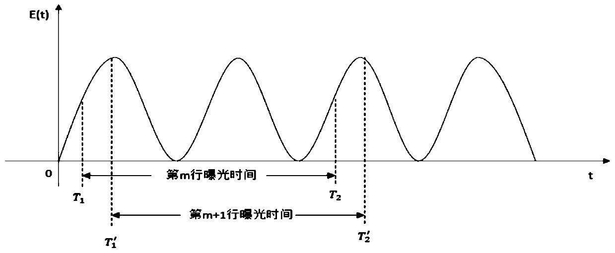
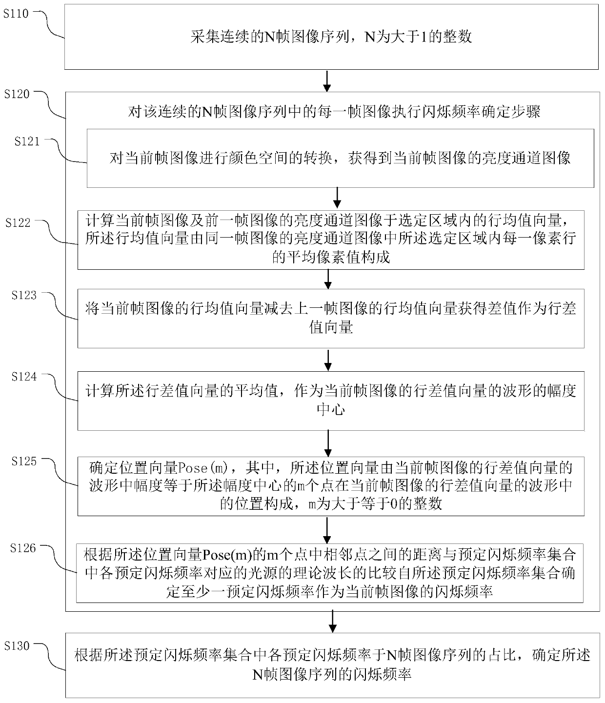
The invention provides a method for detecting image flicker stripes and a method for adjusting image exposure time. The method for detecting the image flicker stripes comprises: S110, collecting N continuous image sequences, N being an integer larger than 1, S120, executing a flicker frequency determining step on each frame of image in the N continuous image sequences, and the flicker frequency determining step comprises: S121, obtaining a brightness channel image of a current frame; S122, calculating a line mean vector of the adjacent frame images; S123, calculating a row difference vector; S124, calculating an average value of the row difference vector to serve as an amplitude center of a waveform of the row difference vector of the current frame image; S125, determining a position vector Pose (m); S126, determining at least one predetermined flickering frequency from the predetermined flickering frequency set as the flickering frequency of the current frame of image; and S130, determining the flicker frequency according to the proportion of each predetermined flicker frequency in the predetermined flicker frequency set in the N frames of image sequences. According to the method,the existence and the frequency of flickering in the image frame sequence can be efficiently and accurately detected.

Description


Claims


Application Information

Patent Timeline
Owner CHENGDU LIGHT COLLECTOR TECH
Why Eureka
Try Eureka