Tag tracking

a positioning system and positioning technology, applied in the direction of speed measurement using gyroscopic effects, gyroscope/turn-sensitive devices, reradiation, etc., can solve the problems of phase ambiguity problem, impracticality of using these frequencies, and unsuitable for use in the system for tracking the movement of competitors in a race or similar sporting event, so as to reduce the computational complexity of position calculations and simplify the design or the tag

Inactive Publication Date: 2007-06-05
TURFTRAX GROUP
View PDF80 Cites 78 Cited by
  • Summary
  • Abstract
  • Description
  • Claims
  • Application Information

AI Technical Summary

Benefits of technology

[0014]In a preferred embodiment, the tag is a transmit-only device which is operable to transmit the signal having the first and second frequency components, since this simplifies the design or the tag.
[0015]In another preferred embodiment, separate fixed tags are provided which operate in the same way as the or each mobile tag and are used to re-reference the signals received by the base stations to a common reference clock signal. In this way, the receivers do not need to be synchronised with each other. Preferably the or each fixed tag is located at the same location as a corresponding one of the base stations, since this reduces the computational complexity of the position calculations.

Problems solved by technology

The system described in US '861 has a number of practical problems which make it unsuitable for use in a system for tracking the movement of competitors in a race or similar sporting event.
One of the main problems is that when a single tone is transmitted between the transmitter and the mobile receiver, the distance between the two must be less than the wavelength of the transmitted tone if an absolute position measurement is to be determined.
If this is not the case, then a phase ambiguity problem arises.
However, use of this part of the radio spectrum is highly regulated making it impractical to use these frequencies.
Another alternative is to lower the frequency of the transmitted tones, however this reduces the resolution of the position measurement making it difficult to distinguish between the different competitors of the race.

Method used


Image

  • Tag tracking
  • Tag tracking
  • Tag tracking

Examples


first embodiment

Overview

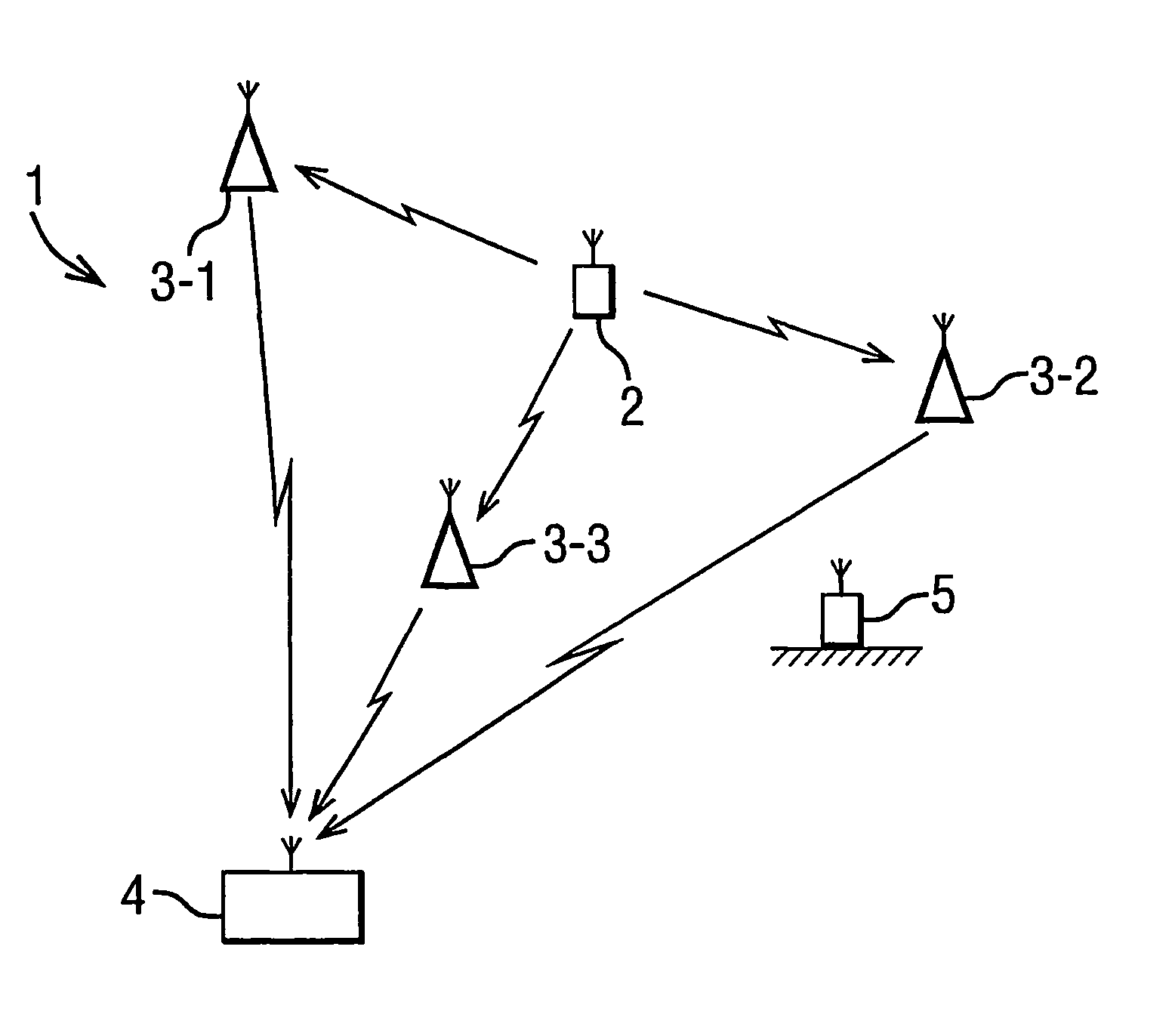
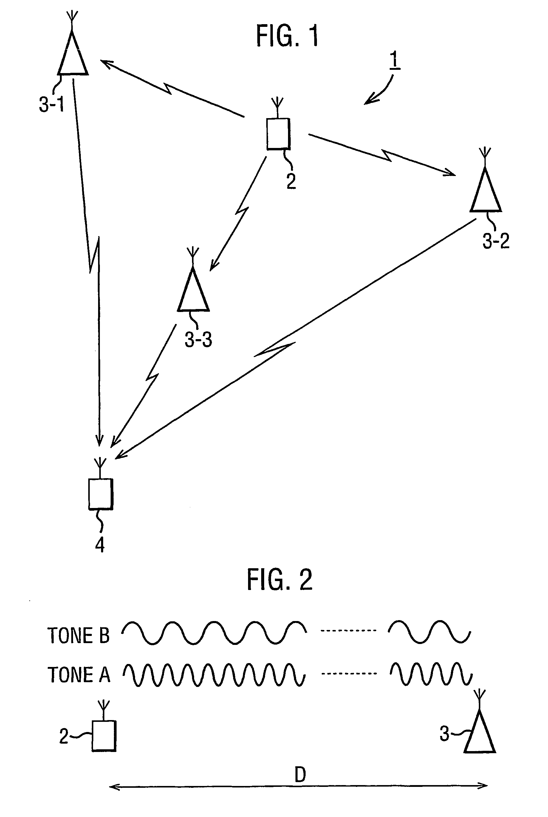
[0042]FIG. 1 illustrates the tracking environment 1 in which the tracking system of the present embodiment operates. The tracking system is used in this embodiment for tracking the position of a mobile tag 2 which is attached to a jockey on a horse (not shown) which is to be tracked. The mobile tag 2 carried by the jockey transmits a signal which is received, in this embodiment, by three fixed receivers 3-1, 3-2 and 3-3. The receivers 3 process the received signals and transmit the processed signals to a position processor 4 which then calculates the position of the mobile tag 2 from the signals received from the receivers 3. In this embodiment, the mobile tag 2 transmits two tones (tone A and tone B) of different frequency which enables the system to be able to determine the absolute position of the mobile tag over a relatively large operating range whilst maintaining position sensing accuracy. The reason for this will now be described with reference to FIG. 2.

[0043]When a ...

second embodiment

[0062]In the first embodiment, it was assumed that the clocks in the tag and in the receivers 3 were synchronised to one another. Whilst this is possible to achieve, it is impractical for most applications. A second embodiment will now be described in which the tag and the receivers are not synchronised. In this embodiment, the mobile tag 2 has the same general architecture as the mobile tag 2 used in the first embodiment. In this embodiment, a network calibration technique is used to account for the lack of synchronisation between the receivers 3. This calibration technique uses signals transmitted from a fixed tag 5 whose position is known and which is constructed and operates in the same way as the mobile tag 2.

[0063]In this embodiment, the processing carried out by the digital signal processor 42 in each receiver 3 is different to the processing carried out in the DSP 42 used in the first embodiment. A more detailed description will now be given of the operation of the ADC 40 an...

third embodiment

[0086]In the first and second embodiments described above, the position of a single mobile tag was determined and then tracked. A third embodiment will now be described in which there is more than one mobile tag 2 to be tracked. FIG. 11 is a schematic flow chart illustrating the operation of this embodiment for tracking N tags simultaneously. At step S11-1, tag 1 transmits a chirp. This chirp is received by receivers 1, 2 and 3 at steps S11-3, S11-5 and S11-7 respectively. Each of the receivers 1, 2 and 3 processes the chirp and transmits the phase measurement data to the position processor. In step S11-9, tag 2 transmits a chirp. This chirp is received by receivers 1, 2 and 3 at steps S11-11, S11-13 and S11-15 respectively. Again, the receivers process the received chirp and transmit the phase measurement data to the position processor. This process continues until the last tag, tag N, transmits a chirp at step S11-17 which chirp is received by the receivers 1, 2 and 3 at steps S11...


PUM


Abstract

The present invention provides a tracking system in which a mobile tag having an unknown position, which tag is to be tracked in space over time, transmits a signal comprising a pair of tones at different frequencies. The transmitted signal is received at each of three receivers, each having a known location, where the phase of each of the tones within the signal is measured. The measured phases are passed to a processing unit which determines the position of the tag at the time of transmission of the signal on the basis of the difference between the measured phases of the two tones. The tracking system operates over a defined finite range to track the position of the mobile tag uniquely in space.

Description

CROSS REFERENCE TO RELATED APPLICATIONS[0001]This application is a National Phase Application based on PCT / GB01 / 05029, filed Nov. 14, 2001, the content of which is incorporated herein by reference, and claims the priority of Great Britain Patent Application Nos. 0027886.1, filed Nov. 15, 2000, 0027888.7, filed Nov. 15, 2000 and 0119787.0, filed Aug. 14, 2001, the content of all of which is incorporated herein by reference.DESCRIPTION[0002]1. Technical Field[0003]This invention relates to a method and apparatus for tracking moving objects. The invention has particular but not exclusive relevance to the tracking of competitors of a race using electronic tags which are carried by the competitors and which transmit signals that are detected by a tracking system.[0004]2. Background Information[0005]There is a requirement for a system to track the movement of competitors in a race or similar sporting event to provide movement data for use in race reconstruction and simulation services. Sp...

Claims


Application Information

Patent Timeline
Patent Type & Authority Patents(United States)
IPC IPC(8): G06F19/00G01S1/08G01S5/02G01S5/14G01S11/02G01S19/21G01S19/26
CPCG01S1/08G01S5/021G01S5/0226G01S5/14G01S11/02A01K15/027
Inventor BARTLETT, DAVIDREYNOLDS, MICHAELSMITH, PAULVASILOPOULOS, NICOLASDUFFETT-SMITH, PETER
Owner TURFTRAX GROUP
Why Eureka
Try Eureka