

Automatic window capable ofpurifying air
A technology for purifying air and windows, applied in the detection field, can solve problems such as accidents and center instability, and achieve the effects of simplifying the structure, optimizing indoor air, and conveniently separating the window sash and hinge unit
- Summary
- Abstract
- Description
- Claims
- Application Information
AI Technical Summary
Problems solved by technology
Method used
Image

Examples
Embodiment Construction
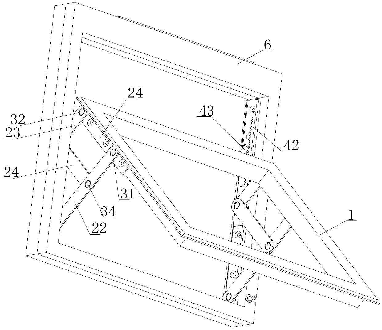
[0040] For the description of the present invention, an automatic window capable of purifying air, the first vertical window edge and the second vertical window edge are two parallel vertical edges of the window frame 6, and the horizontal window edge is the upper and lower frames.
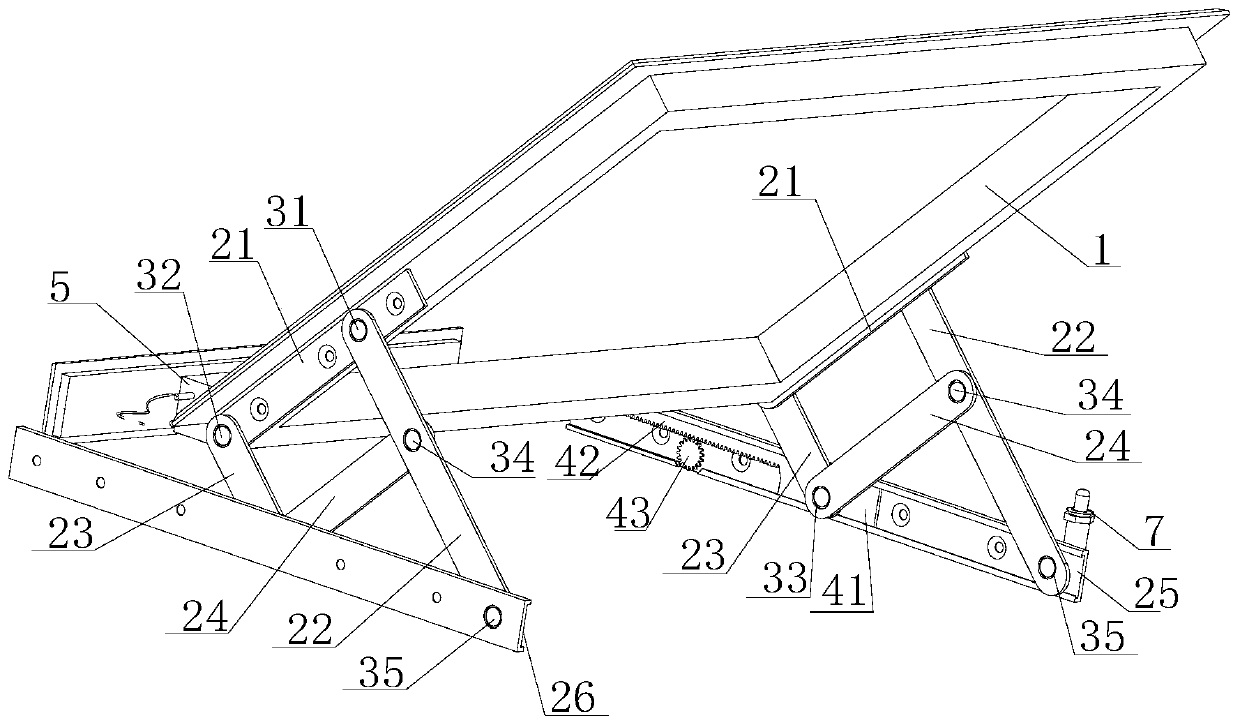
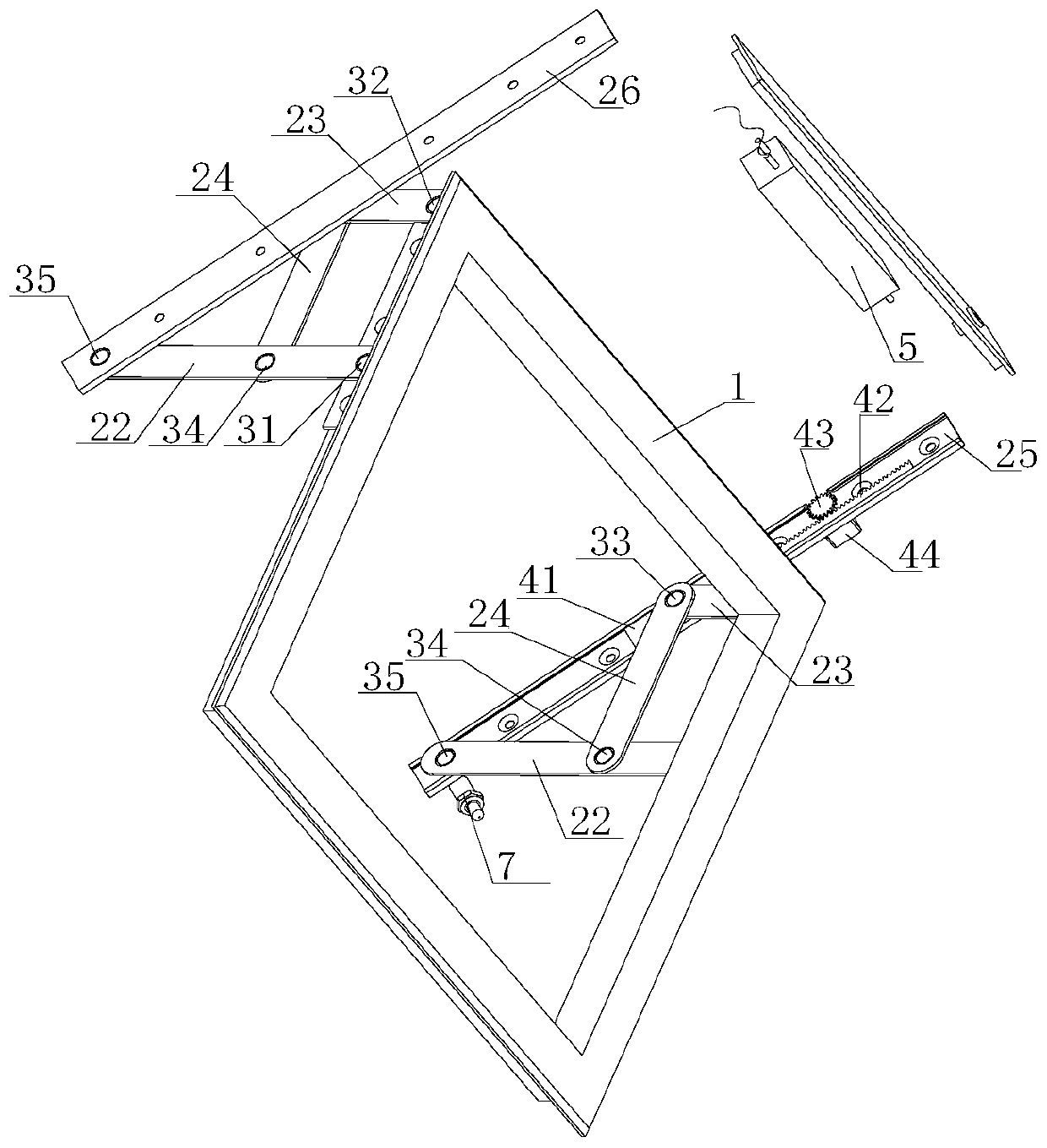
[0041] The window frame 6 and the sash 1 realize the top-hung window through the connection assembly. The present invention adopts the drive mechanism to realize the automatic opening and closing of the window. Here, three connection assemblies and two kinds of drive mechanisms are provided. One of the three connection assemblies and One of these two drive mechanisms can be combined to form an automated window, and the three connection components and the two drive mechanisms will be described separately below.
[0042] First option for connecting components
[0043] Such as Figure 1-3 As shown, the connecting assembly includes a first guide plate 25 arranged on the inner side of the first vertic...
PUM
 Abstract
Description
Claims
Application Information