
Ball push rod and electric bed using same

An electric bed and push rod technology, applied in the field of electric beds, can solve the problems of easy shearing, twisting and damage to the push rod body, and achieve the effect of avoiding twisting damage and reducing shear force

Pending Publication Date: 2019-09-10
泉州极简机器人科技有限公司
View PDF0 Cites 0 Cited by
  • Summary
  • Abstract
  • Description
  • Claims
  • Application Information

AI Technical Summary

Problems solved by technology

[0003] The main purpose of the present invention is to provide a ball push rod and an electric bed using a ball push rod, which solves the drawbacks of the existing push rod that are easily sheared, twisted and damaged when the push rod is connected to the support.

Method used


Image

  • Ball push rod and electric bed using same
  • Ball push rod and electric bed using same
  • Ball push rod and electric bed using same

Examples


Embodiment Construction

[0019] The following will clearly and completely describe the technical solutions in the embodiments of the present invention with reference to the drawings in the embodiments of the present invention. Apparently, the described embodiments are only some of the embodiments of the present invention, not all of them. Based on the embodiments of the present invention, all other embodiments obtained by persons of ordinary skill in the art without creative efforts fall within the protection scope of the present invention.

[0020] It should be noted that all directional indications (such as up, down, left, right, front, back...) in the embodiments of the present invention are only used to explain the relationship between the components in a certain posture (as shown in the accompanying drawings). Relative positional relationship, movement conditions, etc., if the specific posture changes, the directional indication will also change accordingly.

[0021] In addition, the description...


PUM


Abstract

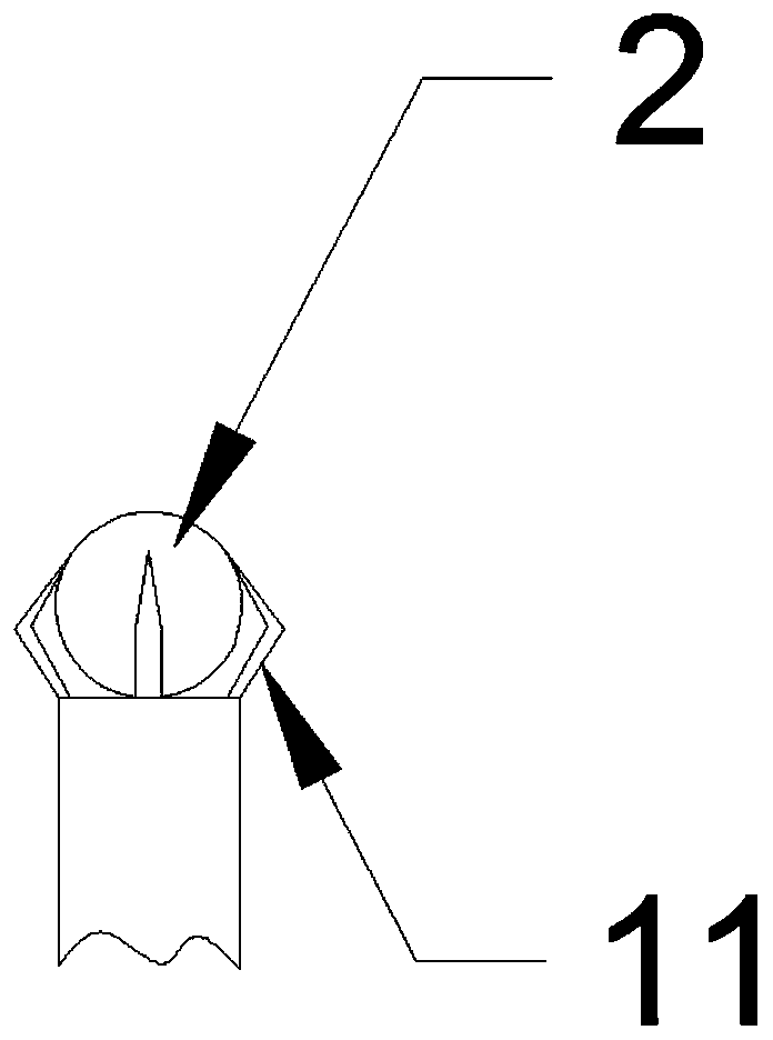
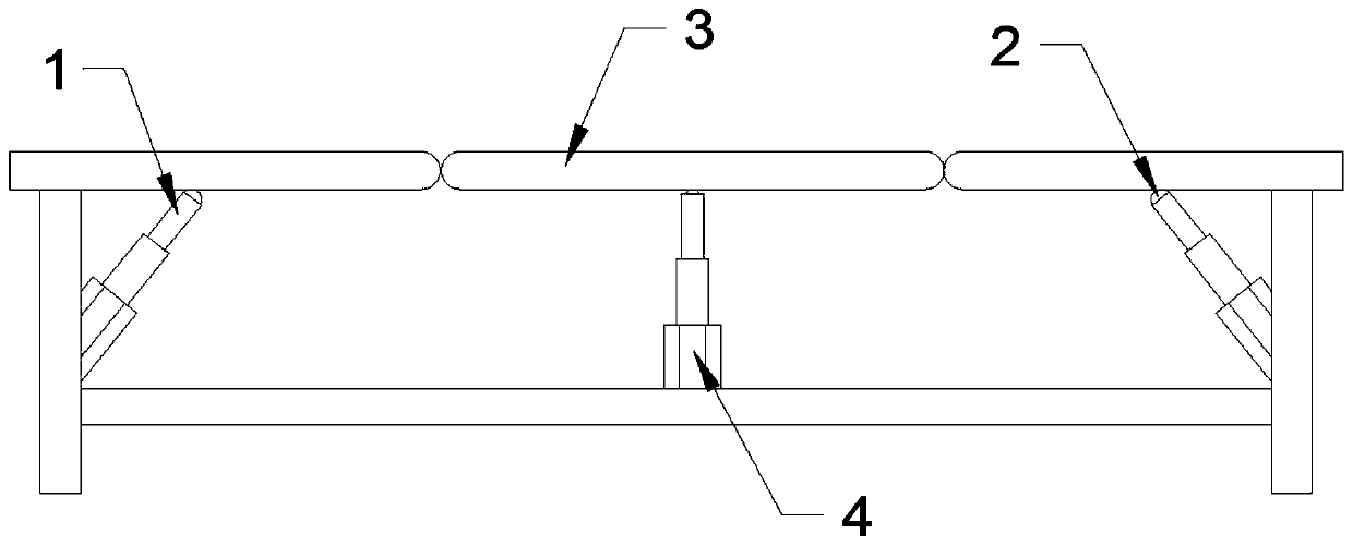
The invention discloses a ball push rod and an electric bed using the ball push rod; a first tail end of a push rod main body is connected with a drive device, a second tail end is provided with an embedding structure, and a ball capable of rolling universally is embedded in the embedding structure. The ball push rod is in abut joint with the back surface of a bed board of the electric bed throughthe ball, so that when the ball push rod pushes the bed board to displace correspondingly, any movement of the bed board in the vertical plane relative to the ball push rod does not cause lateral shearing and twisting to the push rod, and the shearing force generated when the bed board is tilted relatively to the ball push rod can be greatly reduced, and the distortion and damage of the ball pushrod can be avoided.

Description

technical field [0001] The invention relates to the technical field of push rods, in particular to a ball push rod and an electric bed using the ball push rod. Background technique [0002] As a kind of actuator, the push rod is widely used in various scenes in life, such as window opening, medical bed, electric wheelchair and other fields. One end of the push rod is hard-connected to the support, and the other end is connected to the driving device such as the motor. The driving device drives the power transmission device, such as a screw, worm gear, etc., to transmit power to the piston rod to realize the piston movement of the push rod. Since the end of the existing push rod connected to the support is a plane, when the push rod is supporting the support, if the support is deflected or horizontally displaced, it will cause lateral shearing and damage to the connecting end of the push rod. Twisting makes the push rod easy to damage, which has certain potential safety haza...

Claims


Application Information

Patent Timeline
Patent Type & Authority Applications(China)
IPC IPC(8): F16C11/06A47C20/04
CPCF16C11/06A47C20/04F16C2314/70
Inventor 杨松刘南阳
Owner 泉州极简机器人科技有限公司
Learn More