Rotating device for remote sensing scanning mirror

A technology of rotating device and scanning mirror, which is applied in the field of remote sensing, can solve the problems of fixed and single detection scanning range of remote sensing scanners, the impact of range and scanning accuracy, and the narrowing of scanning range of remote sensing scanning mirrors, so as to ensure the scanning range and avoid scanning tracks Fixed, improved telemetry scan performance effects

Inactive Publication Date: 2019-09-10
JILIN JIANZHU UNIVERSITY
View PDF3 Cites 0 Cited by
  • Summary
  • Abstract
  • Description
  • Claims
  • Application Information

AI Technical Summary

Problems solved by technology

[0002] The current remote sensing scanning mirror is usually used directly after the scanning mirror is fixed in advance, which leads to a relatively fixed and single detection scanning range of the remote sensing scanner, which cannot realize omni-directional scanning, thereby reducing the scanning range of the remote sensing scanning mirror and affecting remote sensing. The scanning range of the ordinary scanning rotation device, which only performs swing scanning in one direction, so that, on the one hand, its scanning range is only limited to the range of the swing angle; on the other hand, since remote sensing is often used in aircraft, its In flight, the scanning range and scanning accuracy are greatly affected

Method used


Image

  • Rotating device for remote sensing scanning mirror
  • Rotating device for remote sensing scanning mirror
  • Rotating device for remote sensing scanning mirror

Examples


Embodiment Construction

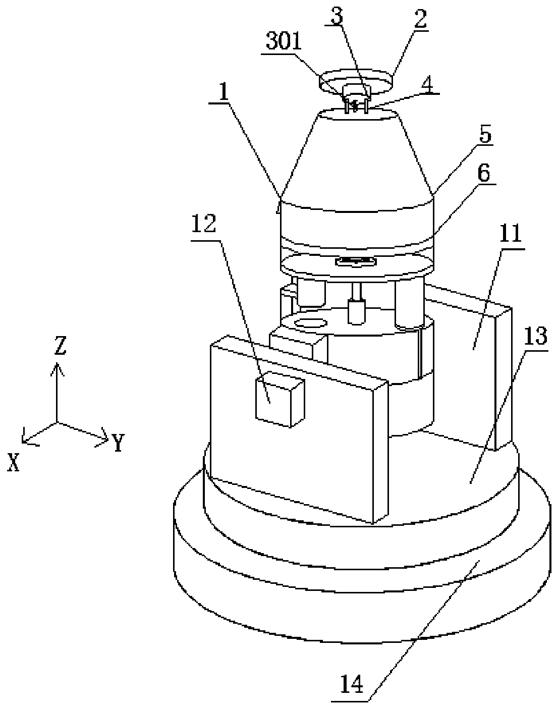
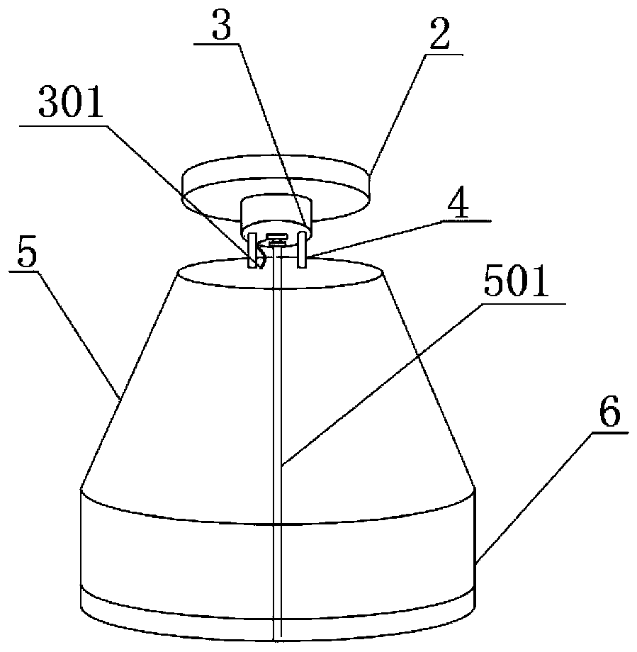
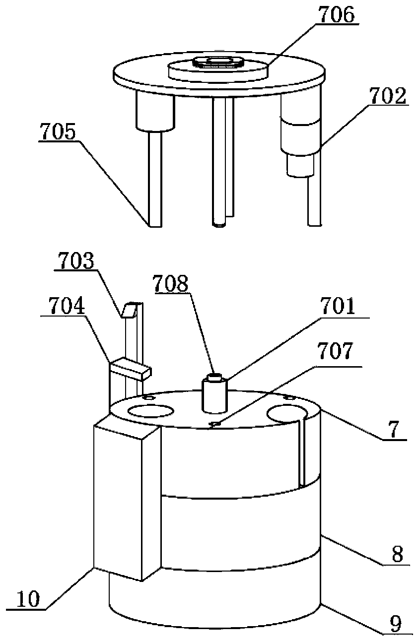
[0024] see Figure 1~3 , in an embodiment of the present invention, a remote sensing scanning mirror rotation device includes a rotating device main body 1, a scanning mirror 2, a fixed seat 11, a rotating disk 13 and a fixed disk 14, wherein the fixed disk 14 can be vertically The rotating disk 13 is installed on the central axis of the rotating disk, and the fixed seat 11 extending vertically is fixedly arranged on the rotating disk. The top of the rotating device main body 1 is provided with the scanning mirror 2; it is characterized in that the rotation of the rotating disk 13 relative to the fixed disk 14 is an intermittent rotation; and the rotating device main body 1 is a reciprocating swing; Including a controller, the controller controls the scanning mirror 2 in each scanning cycle, so that the rotating disk first rotates an intermittent angle, and then controls the main body of the rotating device 1 to swing back and forth, and then makes the rotation The disc rotat...


PUM


Abstract

The invention discloses a rotating device for a remote sensing scanning mirror. In each scanning cycle of the scanning mirror, a rotating disk rotates an intermittent angle first, controls the main body of the rotating device to swing back and forth and rotates the rotating disk by an intermittent angle again, and such sequential cycle makes the rotating disk rotate 360 degrees to complete a scanning cycle, thereby ensuring the comprehensiveness, stability and order of the remote sensing scanning while ensuring the scanning range, and improving the remote sensing scanning performance. The rotating device provided by the invention can adjust the deflection of the adjusting block through a universal shaft and a universal joint, thereby adjusting the angle of the scanning mirror and wideningthe scanning range. By forming a lightweight metal surface glass in the invention, the lightweight metal surface vitrified mirror effectively laminates the lightweight metal with the large-area glassfor precision optical processing of the large-area glass and then plating of an infrared reflective film. Such mirror has high lightweight rate, and the high rigidity, high thermal conductivity and large-area glass has the excellent characteristic of being easy to precision optical processing.

Description

technical field [0001] The invention relates to the technical field of remote sensing, in particular to a remote sensing scanning mirror rotating device. Background technique [0002] The current remote sensing scanning mirror is usually used directly after the scanning mirror is fixed in advance, which leads to a relatively fixed and single detection scanning range of the remote sensing scanner, which cannot realize omni-directional scanning, thereby reducing the scanning range of the remote sensing scanning mirror and affecting remote sensing. The scanning range of the ordinary scanning rotation device, which only performs swing scanning in one direction, so that, on the one hand, its scanning range is only limited to the range of the swing angle; on the other hand, since remote sensing is often used in aircraft, its In flight, the scanning range and scanning accuracy are greatly affected. [0003] Therefore, the present invention provides a remote sensing scanning mirror...

Claims


Application Information

Patent Timeline
Patent Type & Authority Applications(China)
IPC IPC(8): G02B26/10
CPCG02B26/105
Inventor 肖扬尹楠赵鹤
Owner JILIN JIANZHU UNIVERSITY
Why Eureka
Try Eureka