Method, device and storage medium for determining display area

A technology for displaying areas and determining methods, applied in branch equipment, instruments, transmission systems, etc., can solve problems such as unsatisfactory, inability to ensure high-quality transmission of wireless communication data, and achieve high-quality transmission and improve EMC electromagnetic compatibility performance. Effect

Active Publication Date: 2020-09-04
XIAN YIPU COMM TECH
View PDF9 Cites 0 Cited by
  • Summary
  • Abstract
  • Description
  • Claims
  • Application Information

AI Technical Summary

Problems solved by technology

[0004] The technical problem to be solved by the present invention is that none of the schemes used in the prior art to reduce the interference of the LCD display screen to the radio frequency band of the antenna is ideal, and none of them can guarantee the high-quality transmission of wireless communication data and other defects. The purpose is to provide a wireless Method, system, device and storage medium for determining display area of ​​communication device

Method used


Image

  • Method, device and storage medium for determining display area
  • Method, device and storage medium for determining display area
  • Method, device and storage medium for determining display area

Examples


Embodiment 1

[0084] The wireless communication device in this embodiment includes a display module and at least one radio frequency module.

[0085] Among them, the display module includes but is not limited to LCD display screens, etc., the wireless communication equipment includes mobile phones, tablet computers, etc., and the radio frequency module is generally an antenna.

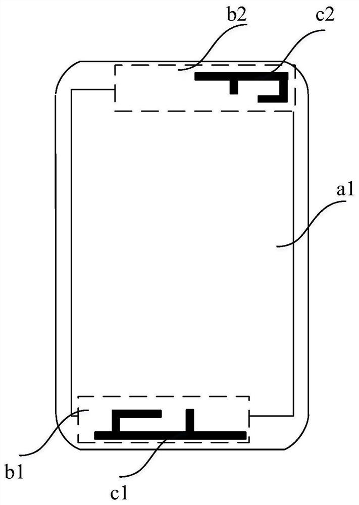
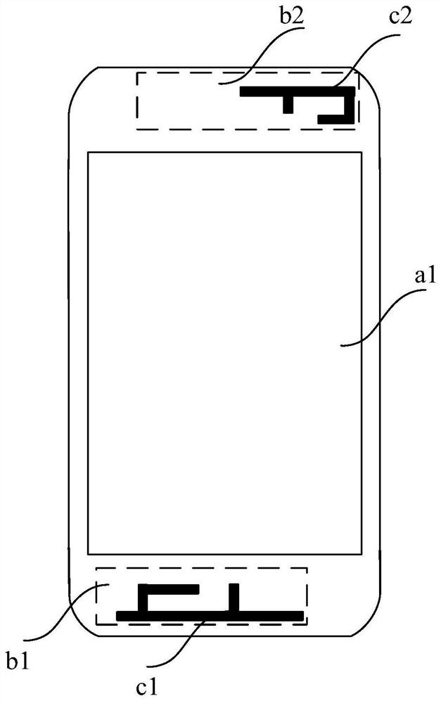
[0086] Such as figure 1 As shown, a1 indicates the initial display area of ​​the LCD display screen, b1 indicates the corresponding projection area of ​​the antenna c1 on the xy plane, and b2 indicates the corresponding projection area of ​​the antenna c2 on the xy plane.

[0087] Both the projection area b1 corresponding to the antenna c1 and the projection area b2 corresponding to the antenna c2 overlap with the initial display area a1 of the LCD display, and obviously the LCD display will interfere with the radio frequency module. Specifically, due to the relatively poor physical isolation between the LCD displa...

Embodiment 2

[0102] Such as Figure 5 As shown, the method for determining the display area of ​​the wireless communication device in this embodiment is a further improvement on Embodiment 1, specifically:

[0103] Step S103 includes:

[0104] S1031. When the radio frequency module is working at the target operating frequency, obtain the interference degree of each pixel on the display module to the radio frequency module;

[0105] Specifically, the first signal strength corresponding to each pixel on the display module during the screen-off test and the corresponding second signal strength during the screen-on test are respectively obtained;

[0106] calculating the difference between the first signal intensity and the second signal intensity corresponding to each pixel;

[0107] Determine the degree of interference of each pixel to the radio frequency module according to the difference;

[0108]Among them, the difference is positively correlated with the degree of interference.

[01...

Embodiment 3

[0115] Such as Figure 6 As shown, the method for determining the display area of ​​the wireless communication device in this embodiment is a further improvement on Embodiment 2, specifically:

[0116] After step S103, before step S104 also includes:

[0117] S1040. Determine whether the target interference area is a rectangular area, and if not, perform fitting processing on the target interference area until the target interference area is fitted into a rectangular area.

[0118] Step S104 includes:

[0119] S1041. Select a plurality of first boundary points on the boundary corresponding to the target interference area, wherein the area formed by the plurality of first boundary points is the target interference area;

[0120] S1042. Obtain first boundary point coordinate data of each first boundary point on the display module;

[0121] S1043. Select a plurality of second boundary points on the boundary corresponding to the initial display area, wherein the area formed by ...


PUM


Abstract

The invention discloses a display area determination method and system and a device and a storage medium. The method comprises the following steps: acquiring a working frequency band corresponding toa radio frequency module; acquiring a target working frequency point interfered by the display module in the working frequency band; obtaining a target interfered area interfered by the display modulewhen the radio frequency module works at the target working frequency point; and removing the target interfered area in the initial display area, and obtaining a target display area corresponding tothe display module when the radio frequency module works at the target working frequency point. According to the invention, when the display module is in a working state, the display module and the radio frequency module are dynamically and physically isolated, so that the interference of the display module on the radio frequency module is minimum or even no interference is generated, thereby improving the EMC electromagnetic compatibility of the whole wireless communication equipment and ensuring high-quality transmission of wireless communication data.

Description

technical field [0001] The present invention relates to the technical field of wireless communication devices, in particular to a method, system, device and storage medium for determining a display area of ​​a wireless communication device. Background technique [0002] With the evolution of radio frequency technology, wireless communication equipment is becoming more and more complex. On the one hand, the current wireless communication equipment involves more and more frequency bands, and its performance requirements for antennas are becoming more and more stringent; on the other hand, the antenna environment is getting worse, such as high screen-to-body ratio and full screen requirements, Various sensors are integrated in the LCD (Liquid Crystal Display), which causes the antenna to be seriously interfered with when the LCD is working (even when the LCD screen is off), making it impossible to achieve EMC (Electro Magnetic Compatibility (electromagnetic compatibility) coex...

Claims


Application Information

Patent Timeline
Patent Type & Authority Patents(China)
IPC IPC(8): G06F1/16H04M1/725
CPCG06F1/1656H04B15/00H04M1/72454
Inventor 李伟
Owner XIAN YIPU COMM TECH
Why Eureka
Try Eureka