Supercharge Your Innovation With Domain-Expert AI Agents!

Apparatus for removal of particulates from air

A particle, air technology, applied in the direction of respiratory filters, clothing, applications, etc.

Inactive Publication Date: 2019-09-10
TURBINATE TECH LTD
View PDF6 Cites 2 Cited by
  • Summary
  • Abstract
  • Description
  • Claims
  • Application Information

AI Technical Summary

Problems solved by technology

The same disadvantage arises in terms of flow resistance and there is also a continuing need for more efficient removal of particulates as products are known to not be fully effective, especially with smaller sized particulates

Method used


Image

  • Apparatus for removal of particulates from air
  • Apparatus for removal of particulates from air
  • Apparatus for removal of particulates from air

Examples


Embodiment Construction

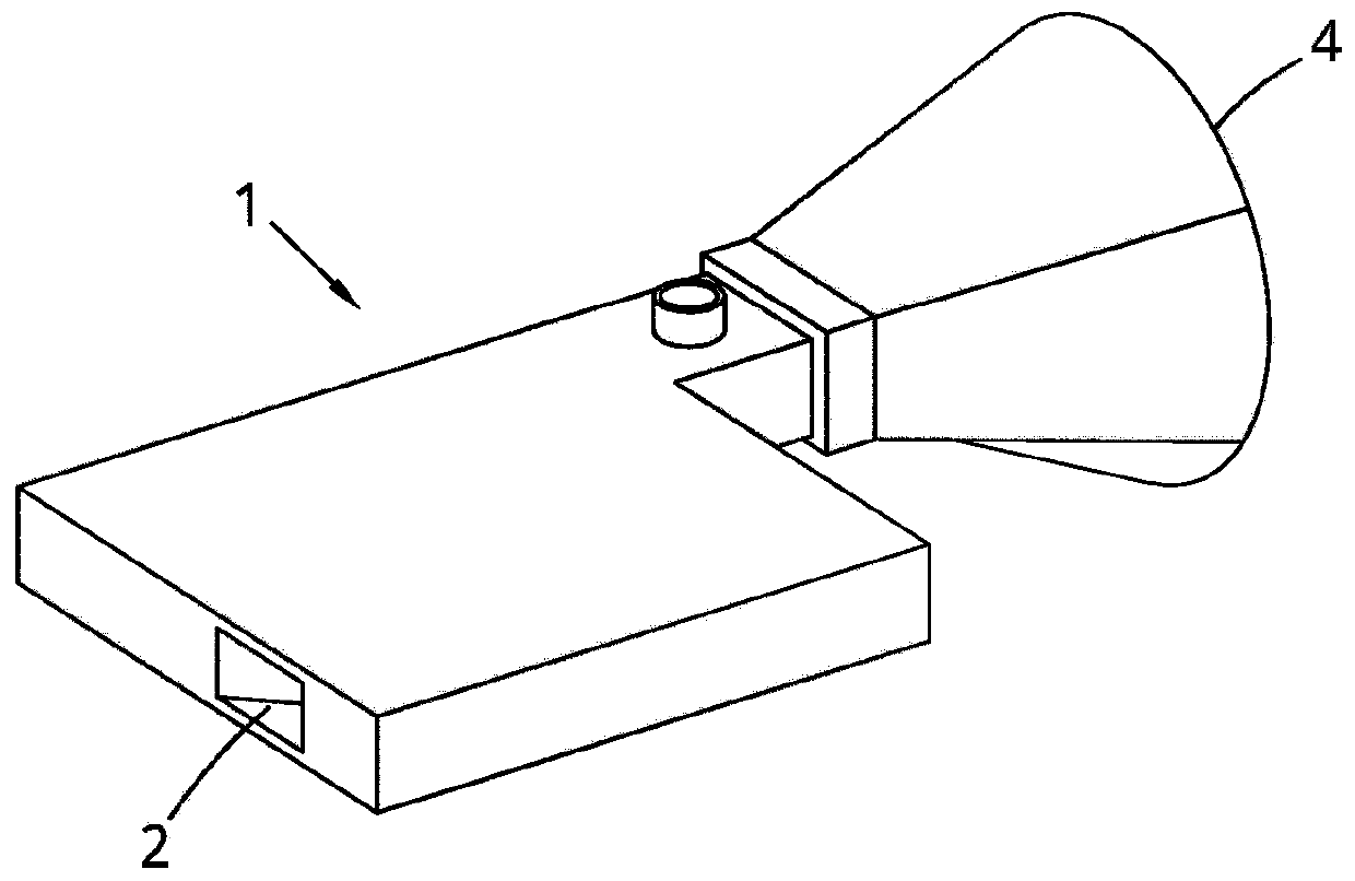
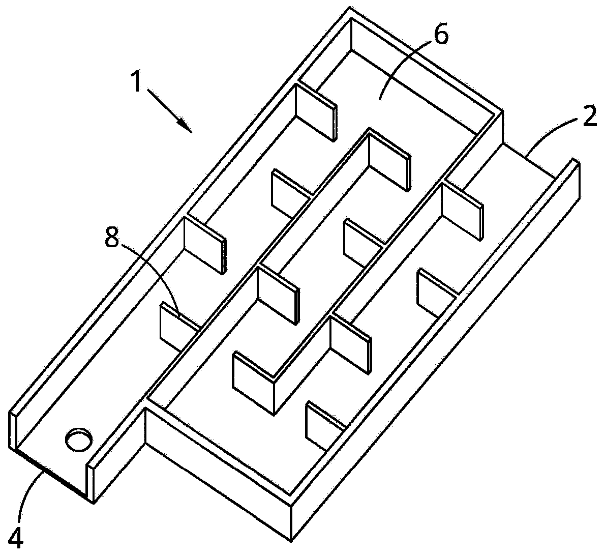
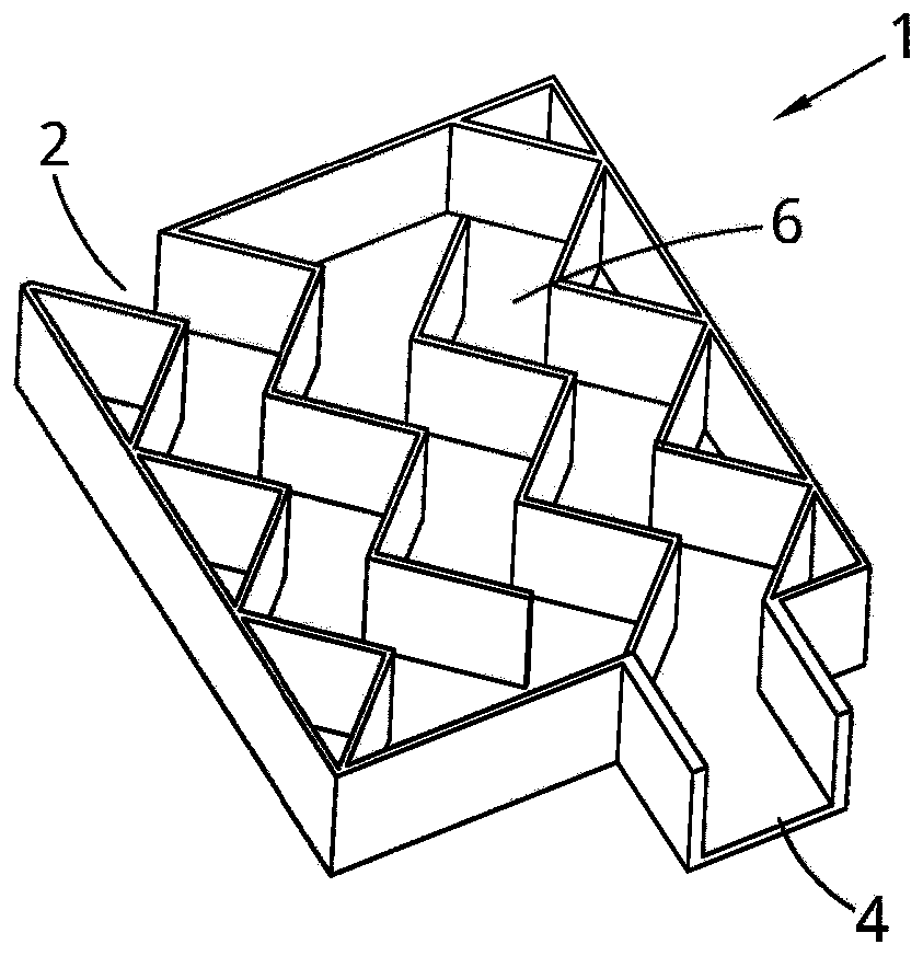
[0168] figure 1 A device 1 for removing particles from a gas is shown. The device 1 comprises an inlet 2 for receiving a gas flow and an outlet 4 through which the gas flow can be discharged. Between the inlet 2 and the outlet 4 is a labyrinth path 6 for air flow to pass through. The labyrinth path 6 is arranged to direct the gas flow so that when the gas flows from the inlet 2 to the outlet 4, particles in the gas will hit the adsorption surface of the labyrinth path 6 - the adsorption surface is arranged to adsorb the impacted particles so that the gas Particles in the gas are removed from the gas by impacting the adsorption surface. There may also be air flow rates below 1 ms in the device 1 -1 and / or less than 10% of the mean input air velocity. These regions may be referred to as slow flow regions. The volume of the slow flow region in the device 1 may be at least 4% of the total volume of the device 1 . The figures show a device with a cone at the outlet 4 . This ...


PUM


Abstract

A device for removal of particulates from a gas is provided. The device comprises: an inlet for receiving a flow of gas; an outlet from which the flow of gas can be expelled; and a labyrinthine path extending between the inlet and the outlet for passage of the flow of gas; wherein the labyrinthine path is arranged to steer the flow of gas such that particulates in the gas will impact on adsorptionsurfaces of the labyrinthine path arranged for adsorption of impacted particulates such that particulates in the gas are removed from the gas by impaction on the adsorption surfaces as the gas flowsfrom the inlet to the outlet. The device may be part of a face mask. The volume of air in the device with a velocity magnitude below 1 ms- 1 may be greater than 4% of the total volume of air in the device.

Description

technical field [0001] The present invention relates to a device for removing particles from a gas, such as a mask, and an associated method for removing particles from a gas. The gas may be air from which particles are removed. For example, this prevents particles from entering a person's lungs during breathing or from releasing them into the atmosphere. Background technique [0002] Particulates in air and other gases are a particularly troublesome form of pollution because they often cannot be easily removed by chemical means such as catalytic converters. In urban areas, the main source of particulate pollution in the air is vehicle exhaust, and diesel vehicles in particular are known to generate large quantities of small-sized particles, including the so-called PM 10 Particles and smaller particles (PM 5 , PM 2.5 , PM 1.0 or smaller, known as "ultrafine particles"). Particulates are a particularly dangerous form of air pollution because they can penetrate deep into...

Claims


Application Information

Patent Timeline
IPC IPC(8): A62B23/02B01D45/04
CPCA62B23/02B01D45/04A41D13/11A62B23/025B01D45/08
Inventor 修·蒙格马利约瑟夫·格雷本·克罗克斯福德
Owner TURBINATE TECH LTD
Features
  • R&D
  • Intellectual Property
  • Life Sciences
  • Materials
  • Tech Scout
  • Unparalleled Data Quality
  • Higher Quality Content
  • 60% Fewer Hallucinations
Learn More