A device for separating and collecting waste dry batteries and button batteries
A button battery and collection device technology, which is applied in the direction of solid separation, classification, chemical instruments and methods, etc., can solve the problems of collection, inability to separate waste dry batteries and button batteries, etc.
- Summary
- Abstract
- Description
- Claims
- Application Information
AI Technical Summary
Problems solved by technology
Method used
Image
Examples
specific Embodiment approach 1
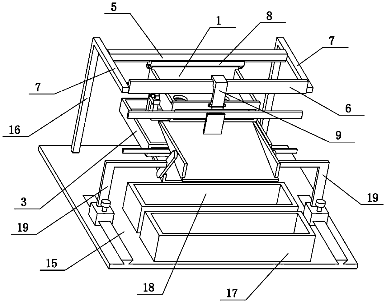
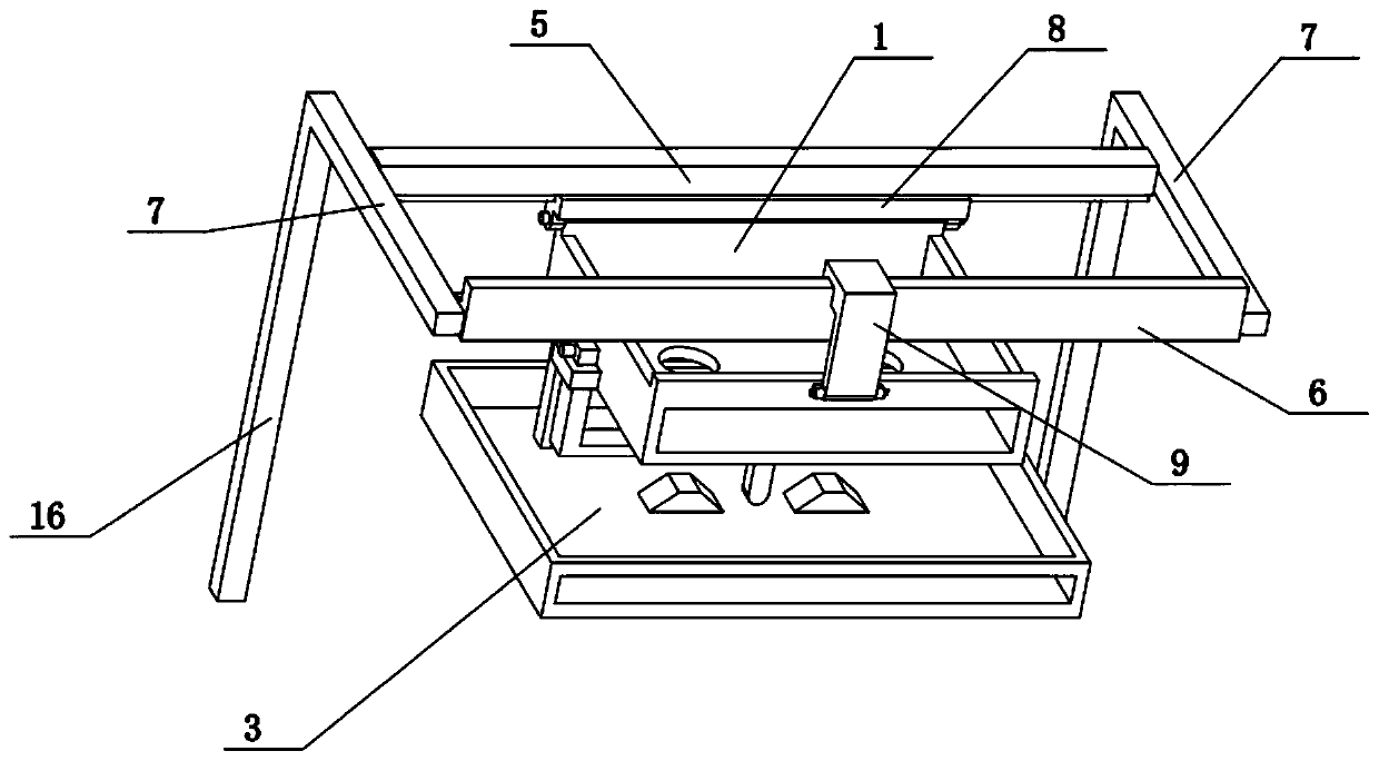
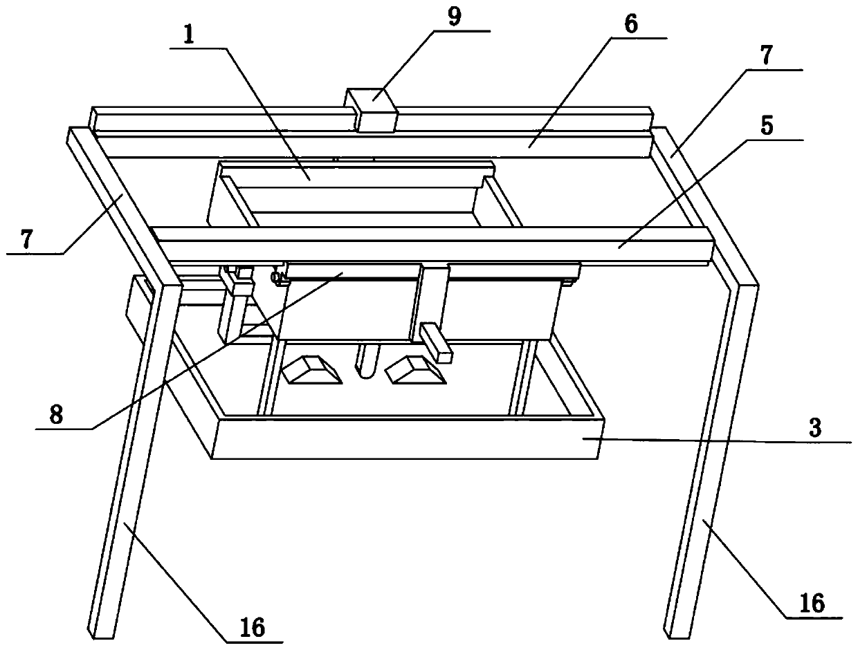
[0039] Combine below Figure 1-18 To illustrate this embodiment, the present invention relates to the field of waste battery treatment, more specifically, a device for separating and collecting waste dry batteries and button batteries, including an upper box body 1, a circular through hole 101, a connecting vertical bar 2, and a lower box body 3 , round baffle 4, short rod 401, the present invention can effectively separate and collect waste dry batteries and button batteries.
[0040]The bottom surface of the upper box body 1 is provided with a plurality of circular through-holes 101, and each circular through-hole 101 is provided with a circular baffle 4 directly at the lower end, and a plurality of circular baffles 4 are connected to the upper body by a short rod 401. The lower end of the box body 1 is provided with a lower box body 3 just below the upper box body 1 , and the upper box body 1 and the lower box body 3 are connected by two connecting vertical bars 2 . When i...
specific Embodiment approach 2
[0042] Combine below Figure 1-18 To illustrate this embodiment, the rear beam 5 and the front beam 6 are arranged parallel to each other, the rear beam 5 and the front beam 6 are connected by two square columns 7, and the upper end of the upper box body 1 is slidably connected to the rear beam 5 And on the front beam bar 6. The upper box body 1 can reciprocate and slide left and right on the rear beam bar 5 and the front beam bar 6, and then realize the shaking of the upper box body 1, and separate the columnar dry battery and the button battery.
specific Embodiment approach 3
[0044] Combine below Figure 1-18 To illustrate this embodiment, the slide bar 8 is slidably connected to the lower end of the rear beam 5 through a chute structure, the upper end of the front beam 6 is provided with a rib 601, and the upper end of the L-shaped plate 9 is provided with a rib groove 901, The upper end of the L-shaped plate 9 is slidably connected to the rib 601 through the convex groove 901, the lower end of the L-shaped plate 9 is hingedly connected to the front side of the upper box body 1, and the rear side of the upper box body 1 is hingedly connected to the Lower end of slider 8. The slide bar 8 can slide left and right at the lower end of the back beam bar 5, and the L-shaped plate 9 can slide left and right on the rib 601, and then the upper box body 1 can slide left and right through the slide bar 8 and the L-shaped plate 9, and then the upper The box body 1 shakes; the L-shaped plate 9 can be pulled up from the rib 601, so that the L-shaped plate 9 le...
PUM
 Abstract
Description
Claims
Application Information
 - R&D
- Intellectual Property
- Life Sciences
- Materials
- Tech Scout
- Unparalleled Data Quality
- Higher Quality Content
- 60% Fewer Hallucinations
Browse by: Latest US Patents, China's latest patents, Technical Efficacy Thesaurus, Application Domain, Technology Topic, Popular Technical Reports.
© 2025 PatSnap. All rights reserved.Legal|Privacy policy|Modern Slavery Act Transparency Statement|Sitemap|About US| Contact US: help@patsnap.com


