Waterproof structure on output shaft of speed reducer and speed reducer
A waterproof structure and output shaft technology, which is applied in the direction of mechanical equipment, transmission parts, belts/chains/gears, etc., can solve the problems of box structure rigidity reduction, safety accidents, water corrosion, etc., to eliminate potential safety hazards and prolong service life Lifespan, to ensure the effect of normal use
- Summary
- Abstract
- Description
- Claims
- Application Information
AI Technical Summary
Problems solved by technology
Method used
Image

Examples
Embodiment 1
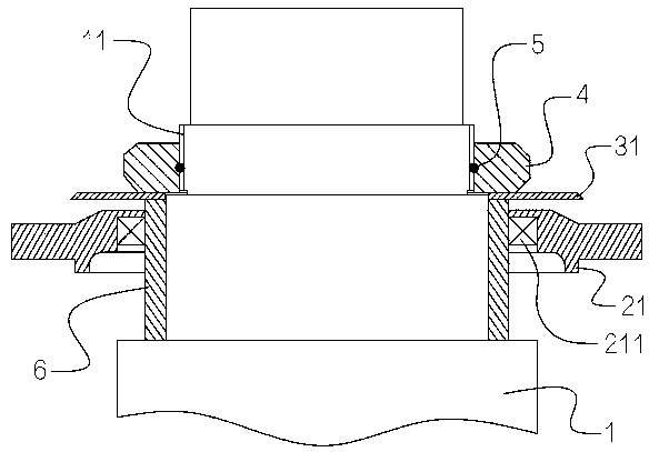
[0023] Such as figure 1 As shown, a waterproof structure at the output shaft of a reducer includes a vertical output shaft 1 and an upper end cover 21, the output shaft 1 passes through the upper end cover 21, the upper end of the output shaft 1 is exposed to the upper end cover 21, and the upper end cover 21 An oil seal 211 is embedded in the inner wall of the shaft, and the part of the output shaft 1 exposed to the upper end cover 21 is sleeved with a circular water throwing pan 31 .
[0024] The part of the output shaft 1 exposed to the upper end cover 21 is provided with an external thread section 11, and a round nut 4 is threaded on the external thread section 11. An O-ring seal 5 is sandwiched between the round nut 4 and the external thread section 11. The output shaft 1 The position below the outer thread section 11 on the outside is fixedly sleeved with a wear-resistant bushing 6 , and the water thrower 31 is clamped between the round nut 4 and the wear-resistant bushi...
Embodiment 2
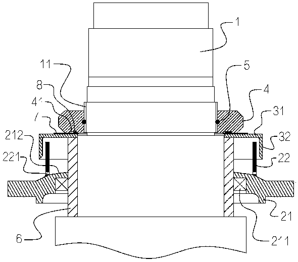
[0028] This embodiment is improved on the basis of the first embodiment. Such as figure 2 As shown, a cylindrical water retaining ring 32 coaxially extends downward from the outer edge of the water throwing pan 31 . The water retaining ring 32 and the water throwing pan 31 of this embodiment are welded together in a full welded manner, so that a sealing effect can be achieved at the junction of the water retaining ring 32 and the water throwing pan 31 . In other embodiments, the water retaining ring and the water throwing pan 31 can also be integrally processed and formed. The water retaining ring 32 can increase the shielding area three-dimensionally, further enhancing the waterproof effect.
[0029] The top of the upper end cover 21 in this embodiment extends upwards a cylindrical isolation tube 22, the isolation tube 22 is coaxial with the inner circular hole of the upper end cover 21, the isolation tube 22 is inserted into the water retaining ring 32, and the isolation ...
Embodiment 3
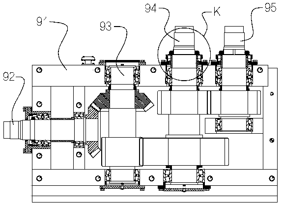
[0034] Such as image 3 with Figure 4 As shown, this embodiment introduces a reducer using the waterproof structure in Embodiment 2, including a box body 91, a horizontal input shaft 92, a vertical intermediate transmission shaft 93, a vertical first output shaft 94 and a first vertical output shaft 94. Two output shafts 95. The input shaft 92 , the intermediate transmission shaft 93 , the first output shaft 94 and the second output shaft 95 are respectively rotatably connected to the casing 91 through rolling bearings. The input shaft 92 and the intermediate transmission shaft 93 are connected by a pair of bevel gears, the intermediate transmission shaft 93 and the first output shaft 94 are connected by a pair of helical gears, and the first output shaft 94 and the second output shaft 95 are connected by a pair of helical gears. Drive connection. The output ends of the first output shaft 94 and the second output shaft 95 are all located above the box body 91, and the two ...
PUM
 Abstract
Description
Claims
Application Information
 - Generate Ideas
- Intellectual Property
- Life Sciences
- Materials
- Tech Scout
- Unparalleled Data Quality
- Higher Quality Content
- 60% Fewer Hallucinations
Browse by: Latest US Patents, China's latest patents, Technical Efficacy Thesaurus, Application Domain, Technology Topic, Popular Technical Reports.
© 2025 PatSnap. All rights reserved.Legal|Privacy policy|Modern Slavery Act Transparency Statement|Sitemap|About US| Contact US: help@patsnap.com