Extendable type tail apron mechanism

An expansion, skirt technology, applied in the direction of projectiles, self-propelled bombs, offensive equipment, etc., can solve problems such as the deterioration of missile or rocket stability, reduce the pressure center coefficient, high stability, and increase the expansion angle. Effect

Inactive Publication Date: 2019-09-13
HARBIN INST OF TECH
View PDF7 Cites 4 Cited by
  • Summary
  • Abstract
  • Description
  • Claims
  • Application Information

AI Technical Summary

Problems solved by technology

[0004] The present invention provides an expandable tail skirt mechanism in order to solve the problem that the stability of missiles or rockets deteriorates as the Mach number increases during high-speed flight of existing missiles or rockets.

Method used


Image

  • Extendable type tail apron mechanism
  • Extendable type tail apron mechanism
  • Extendable type tail apron mechanism

Examples


specific Embodiment approach 1

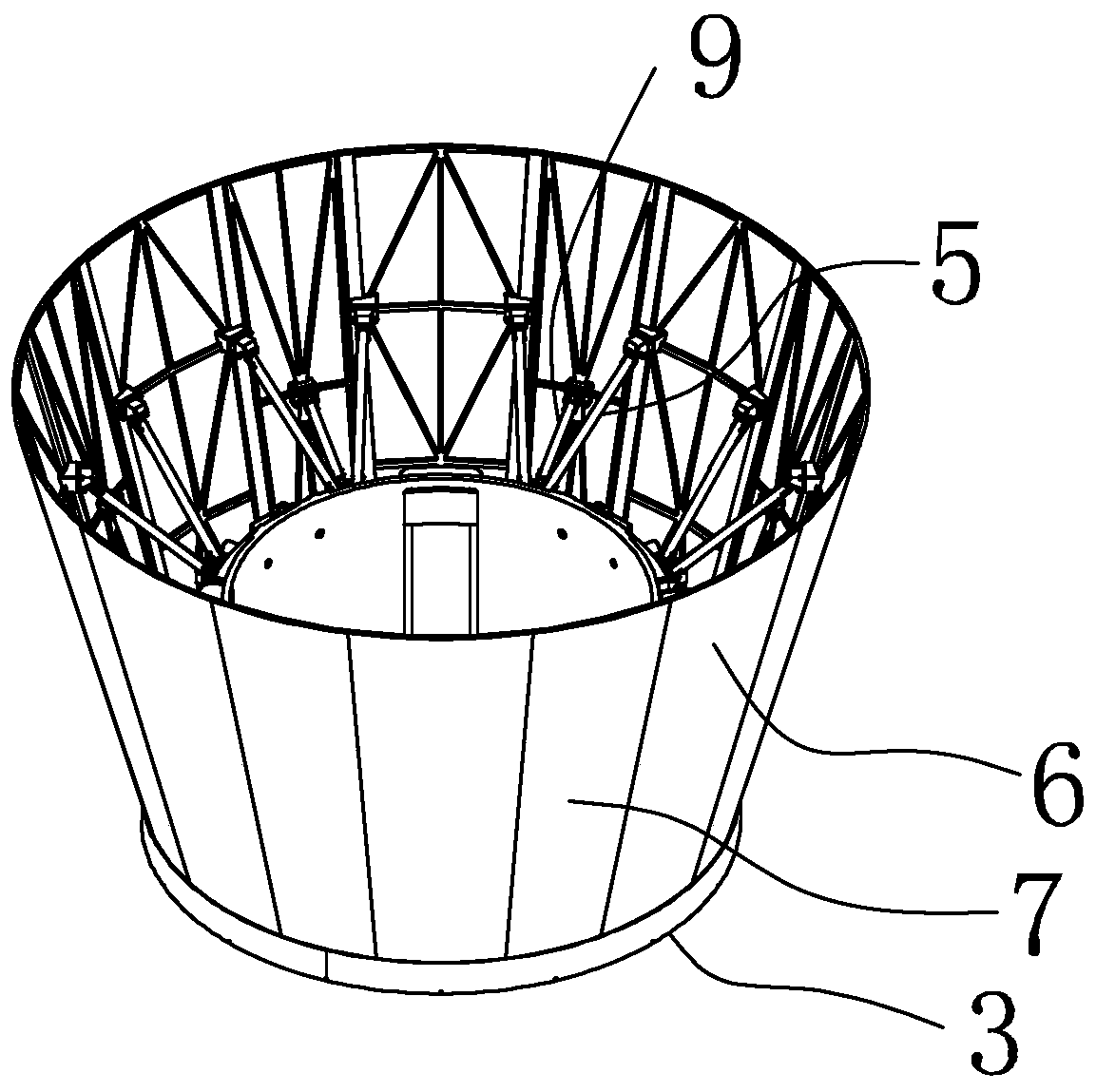
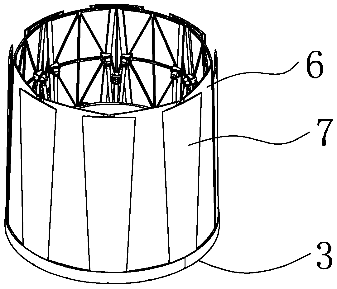
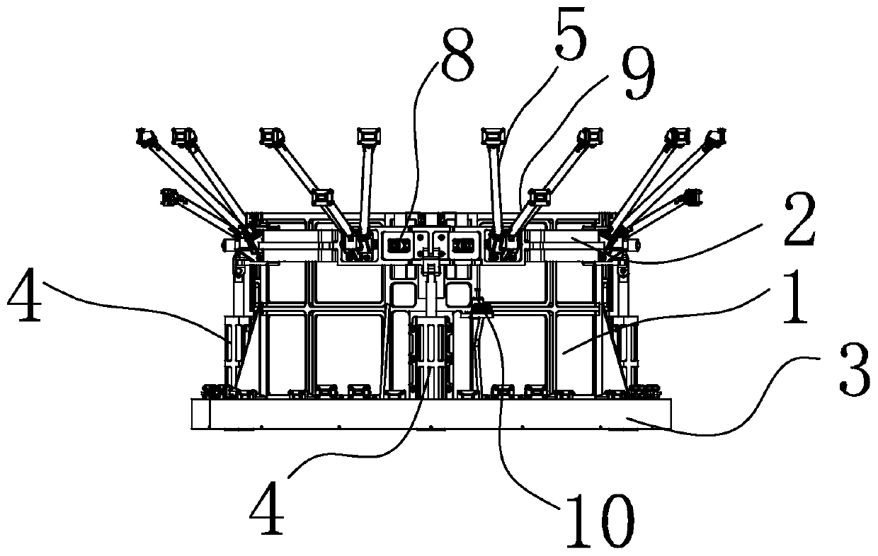
[0025] Specific implementation mode one: combine Figure 1-Figure 6 To illustrate this embodiment, this embodiment includes a circular inner frame body 1, a circular outer frame body 2, a butt flange 3, a plurality of power drive devices 4, a plurality of pairs of long rods 5, a plurality of short rods 9, a plurality of An inner skirt 6, a plurality of outer skirts 7 and a plurality of locking devices 8;

[0026] A plurality of linear guide rails 1-1 are evenly distributed on the outer circumference of the circular inner frame body 1, and a plurality of sliders are evenly distributed on the inner circumference of the circular outer frame body 2, and each slider and each linear guide rail 1-1 The circular inner frame body 1 can move along the axis of the circular outer frame body 2 by cooperating and driven by a plurality of power driving devices 4, and the butt flange 3 is affixed to the circular inner frame body 1 and arranged concentrically , a plurality of inner skirts 6 a...

specific Embodiment approach 2

[0032] Specific implementation mode two: combination image 3 and Figure 5 To illustrate this embodiment, a plurality of pyrotechnic cutters 10 are fixed on the circular inner frame body 1 of this embodiment. When the tail skirt is in a folded state, each pyrotechnic cutter 10 is connected to the The circular outer frame body 2 is connected.

[0033] The model of the pyrotechnic cutter 10 is HG01-02, which was developed by the 508 Institute of the Fifth Academy of Aerospace Science and Technology.

[0034] When the tail skirt is unfolded from the folded state, the screw that connects the pyrotechnic cutter 10 to the circular outer frame body 2 is cut off by the pyrotechnic cutter 10, and the circular outer frame body 2 is driven by a plurality of power drive devices 4 to make the circular The outer frame body 2 moves along the axis of the circular inner frame body 1, so that a plurality of inner skirt pieces 6 and a plurality of outer skirt pieces 7 are unfolded.

[0035] ...

specific Embodiment approach 3

[0036] Specific implementation mode three: combination image 3 , Figure 7 and Figure 8 To illustrate this embodiment, each of the locking devices 8 in this embodiment includes a positioning pin 8-1, a first compression spring 8-2 and a sleeve 8-3;

[0037] The sleeve 8-3 is provided with a shoulder, the first compression spring 8-2 is arranged in the sleeve 8-3, and the positioning pin 8-1 passes through the first compression spring 8-2 and the sleeve 8-3 and passes through the sleeve 8-3. The barrel 8-3 protrudes, and the positioning pin 8-1 is processed with a shaft shoulder. One end of the first compression spring 8-2 is stuck on the shaft shoulder, and the other end of the first compression spring 8-2 is pressed against the sleeve 8-2. 3, the circular outer frame body 2 and the circular inner frame body 1 are respectively processed with positioning pin holes that cooperate with each other, and the positioning pin 8-1 is inserted into the positioning pin of the circula...


PUM


Abstract

The invention discloses an extendable type tail apron mechanism, and belongs to the technical field of aircrafts. The problems that when an existing guided missile or rocket carries out high-speed flying, along with Mach number increasing, the stability of the guided missile or rocket is poor are solved. The mechanism comprises a round inner frame body, a round outer frame body, an abut-joint flange, multiple power driving devices, multiple pairs of long rods, multiple short rods, multiple inner apron pieces, multiple outer apron pieces and multiple locking devices; multiple linear guide railsare evenly distributed on the outer circumference of the round inner frame body, the sliding blocks are evenly distributed on the inner circumference of the round outer frame body, each sliding blockand each linear guide rail are matched, through driving of the power driving devices, the round inner frame body moves along the axis of the round outer frame body, the abut-joint flange is fixedly connected to the round inner frame body and is arranged in a concentric manner, the inner apron pieces and the outer apron pieces are hinged to the abut-joint flange, and are spaced to form a tail apron, and the mechanism is suitable for hypersonic vehicles.

Description

technical field [0001] The invention relates to a tail skirt mechanism, in particular to an expandable tail skirt mechanism, which belongs to the technical field of missiles. Background technique [0002] The highly informationized future war situation is complex and changeable, which puts forward higher requirements for aircraft, making the performance of aircraft develop in the direction of supersonic speed, long distance, and high maneuverability. The premise of achieving all this is that the aircraft can complete the flight under the design conditions without losing stability. Stability is the guarantee for the aircraft to complete its mission safely, and its importance is self-evident. However, maneuverability and stability are contradictory, the enhancement of maneuverability means the weakening of stability, and the problem brought about by the improvement of stability is that the maneuverability is weakened. In the design stage of the aircraft, a trade-off needs to ...

Claims


Application Information

Patent Timeline
Patent Type & Authority Applications(China)
IPC IPC(8): F42B15/00F42B10/06
CPCF42B10/06F42B15/00
Inventor 郭宏伟杨德文杨广边琨刘荣强邓宗全
Owner HARBIN INST OF TECH
Why Eureka
Try Eureka