
Test fixture and test method of dielectric waveguide filter

A dielectric waveguide and test fixture technology, which is applied to the parts, instruments, and measuring electronics of electrical measuring instruments, can solve the complex structure of the test fixture, the complicated connection relationship between the dielectric waveguide filter and the test fixture, and the unfavorable low cost of the test fixture. Simplify the test process and other issues to achieve the effect of improving consistency and stability, simplifying the test process, and simplifying the connection relationship

Inactive Publication Date: 2019-09-13
GUANGDONG GOVA ADVANCED MATERIAL TECH
View PDF5 Cites 4 Cited by
  • Summary
  • Abstract
  • Description
  • Claims
  • Application Information

AI Technical Summary

Problems solved by technology

[0003] When testing dielectric waveguide filters, it is necessary to design special test fixtures. In the prior art, the test fixtures for dielectric waveguide filters usually use adapters, SMP connectors ("board-to-board" coaxial connectors) and test boards. The pattern realizes the structural design of the test fixture, but the structure of the test fixture in this mode is relatively complicated, and the connection relationship between the dielectric waveguide filter and the test fixture is complicated, which is not conducive to the low cost of the test fixture and the simplification of the test process

Method used


Image

  • Test fixture and test method of dielectric waveguide filter
  • Test fixture and test method of dielectric waveguide filter
  • Test fixture and test method of dielectric waveguide filter

Examples


Embodiment Construction

[0032] The following will clearly and completely describe the technical solutions in the embodiments of the application with reference to the drawings in the embodiments of the application. Apparently, the described embodiments are only some of the embodiments of the application, not all of them. Based on the embodiments in this application, all other embodiments obtained by persons of ordinary skill in the art without making creative efforts belong to the scope of protection of this application.

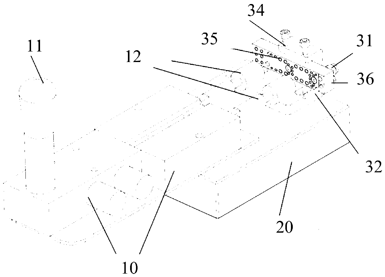
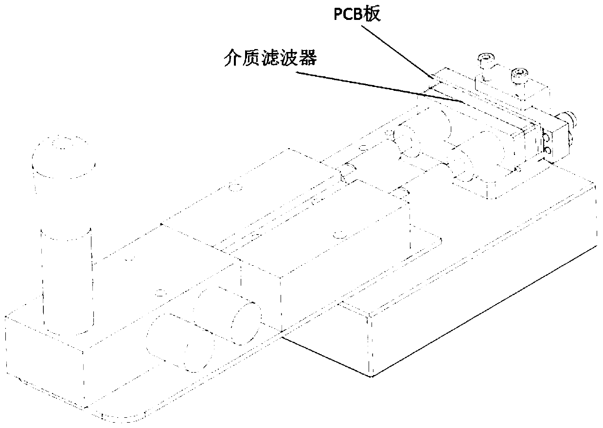
[0033] An embodiment of the present application provides a test fixture for a dielectric waveguide filter, such as figure 1 and figure 2 shown, including:

[0034] Base 20;

[0035] The clamping device and the testing device arranged on the base 20; wherein,

[0036] The clamping device has a translation degree of freedom parallel to the plane of the base 20, the test device is arranged on one side of the clamping device in the translation direction, and the test device and the ...


PUM


Abstract

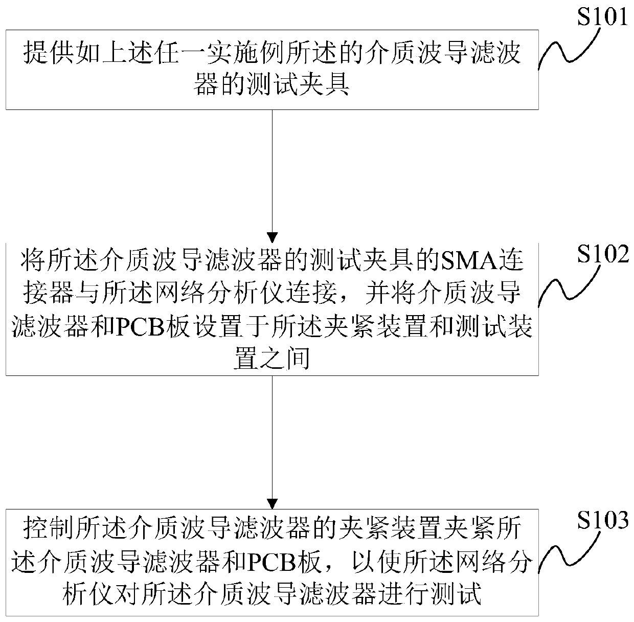
The invention discloses a test fixture and a test method of a dielectric waveguide filter. The test fixture of the dielectric waveguide filter directly uses an SMA (Small A Type) connector to be connected with the dielectric waveguide filter, the connection of the test fixture and the dielectric waveguide filter is realized without the devices such as an adapter, the concrete structure of the testfixture of the dielectric waveguide filter is simplified, and the connected relation between the dielectric waveguide filter and the test fixture of the dielectric waveguide filter is simplified, sothat the test process of the dielectric waveguide filter by using the test fixture of the dielectric waveguide filter is simplified. Moreover, the test fixture of the dielectric waveguide filter alsohas the function of a clamping device for realizing clamping fixation of the dielectric waveguide filter, and the uniformity and stability of the test fixture of the dielectric waveguide filter for the test of the dielectric waveguide filter are improved.

Description

technical field [0001] The present application relates to the technical field of equipment testing devices, and more specifically, to a testing fixture for a dielectric waveguide filter and a testing method thereof. Background technique [0002] Dielectric waveguide filters are filters made of high dielectric constant ceramic materials, which have many advantages such as small size, low loss, small frequency temperature coefficient and thermal expansion coefficient, and high Q value. [0003] When testing dielectric waveguide filters, it is necessary to design special test fixtures. In the prior art, the test fixtures for dielectric waveguide filters usually use adapters, SMP connectors ("board-to-board" coaxial connectors) and test boards. The pattern realizes the structural design of the test fixture, but the structure of the test fixture in this mode is relatively complicated, and the connection relationship between the dielectric waveguide filter and the test fixture is ...

Claims


Application Information

Patent Timeline
Patent Type & Authority Applications(China)
IPC IPC(8): G01R31/00G01R1/04
CPCG01R31/00G01R1/0408
Inventor 杨继聪何钟鑫蒋劲雷龙志勇黄伟杰黄万强
Owner GUANGDONG GOVA ADVANCED MATERIAL TECH
Learn More