
camera operating device

A technology for operating devices and cameras, which is used in selection devices, telemetry/remote selection devices, instruments, etc., and can solve the problems of short data transmission distance, high cable cost, and weak resistance to electrical noise.

Active Publication Date: 2021-01-08
KOWA CO LTD
View PDF9 Cites 0 Cited by
  • Summary
  • Abstract
  • Description
  • Claims
  • Application Information

AI Technical Summary

Problems solved by technology

[0003] For example "CameraLink (registered trademark) standard", it just can realize the supply of 2Gbps image data forwarding, camera control, communication and / or power supply with a single cable, but has the high cost of this cable, and the transmittable distance of data ( The maximum cable length) is short (about 10m)
[0004] In addition, the "GigE Vision (registered trademark) standard" uses a twisted pair cable to achieve a long data transmission distance (about 100m), but even if a shielded twisted pair cable is used, there is a problem of weak resistance to electrical noise
[0005] Furthermore, under the "USB3.0 standard" which is a general-purpose data interface standard, the maximum data transfer speed is a high speed of 5Gbps, but the data transmission distance is short, about 5m

Method used


Image

  • camera operating device
  • camera operating device
  • camera operating device

Examples


Embodiment 1

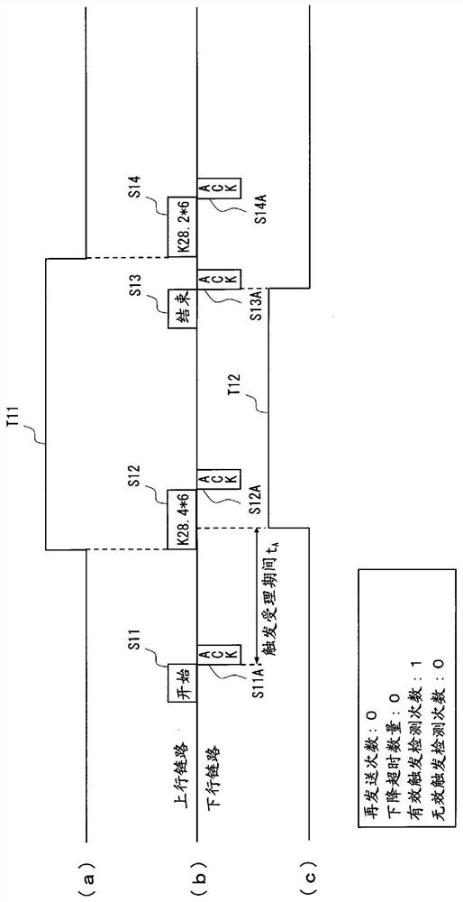
[0077] according to figure 2 Embodiment 1 of the present invention will be described. The symbol T11 in (a) of the figure represents the control-side trigger signal input to the control circuit 3, and the uplink in (b) of the figure represents the transmission of commands from the control circuit 3 to the camera-side circuit 2. Timing, the downlink in (b) of the figure represents the timing of replying to the command from the camera-side circuit 2 to the control circuit 3, and the symbol T12 in (c) of the figure represents that it is sent from the camera-side control circuit 3 to the The camera side trigger signal of the photographing part C.

[0078] First, when a character acceptance start command is issued from the acceptance start command issuing unit 31A of the control circuit 3 (see S11), an acknowledgment (ACK) message is returned from the character receiving unit 21 (see S11A). Therefore, the above-mentioned trigger acceptance period t A start, during the trigger a...

Embodiment 2

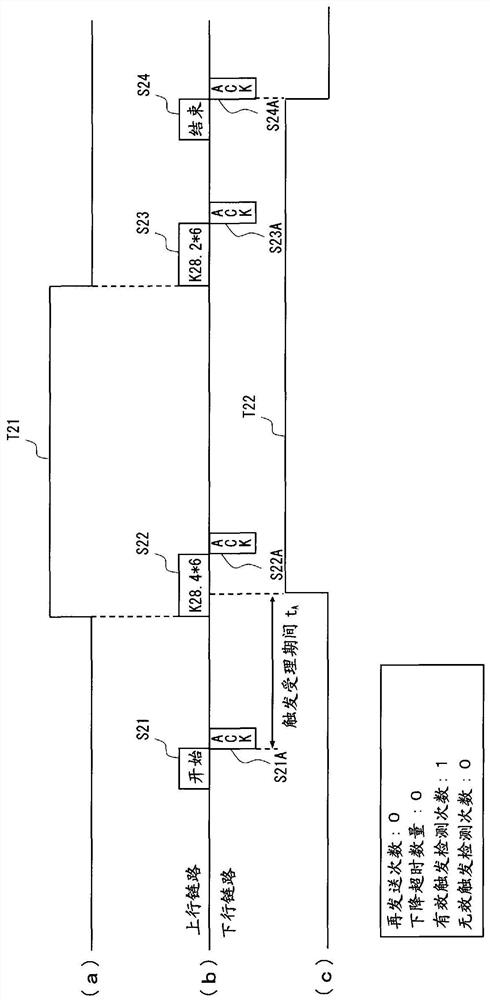
[0080] according to image 3 Embodiment 2 of the present invention will be described.

[0081] exist image 3 In the illustrated pattern, the control-side trigger signal T21 becomes L at a timing earlier than the trigger invalid command issuance timing (see S24), and a falling trigger is issued (see S23), but the camera-side trigger signal T22 The trigger signal T22 on the camera side changes to L without changing to L at the timing when a trigger invalidation command is issued.

Embodiment 3

[0083] according to Figure 4 Embodiment 3 of the present invention will be described.

[0084] exist Figure 4In the example shown, although a dummy command is sent to the character receiving unit 21 before the character acceptance start command is issued by the character acceptance start command issuing unit 31A (see S31), this command is ignored. In addition, although a dummy command is sent to the character receiving unit 21 after the trigger invalidation command is issued (refer to S36), this command is also ignored. Finally, a camera-side trigger signal T32 is issued based on a regular command (see S33).


PUM


Abstract

The object of the present invention is to enable shooting at an appropriate timing. In the camera operation device (1) according to the present invention, when a predetermined command is sent from the control circuit side to the imaging unit side (see S12), a trigger signal is issued (T12) to start imaging. Since issuance of such a trigger signal ( T12 ) is not permitted until a character reception start command is issued, it is possible to perform imaging at an appropriate timing.

Description

technical field [0001] The present invention relates to a camera operating device configured to perform imaging by an imaging unit based on a trigger signal. Background technique [0002] Conventionally, various standards have been established as data communication standards for industrial digital cameras (hereinafter simply referred to as "cameras") (for example, see Non-Patent Document 1), each of which has its own characteristics and problems. [0003] For example "CameraLink (registered trademark) standard", it just can realize the supply of 2Gbps image data forwarding, camera control, communication and / or power supply with a single cable, but has the high cost of this cable, and the transmittable distance of data ( The maximum cable length) is short (about 10m). [0004] In addition, "GigE Vision (registered trademark) standard" realizes a long data transmission distance (approximately 100m) using a twisted pair cable, but even using a shielded twisted pair cable has a...

Claims


Application Information

Patent Timeline
Patent Type & Authority Patents(China)
IPC IPC(8): H04N5/232H04Q9/00
CPCG08C19/02G08C2201/63H04N23/60H04N23/661H04Q9/00H04W84/12H04L5/0055H04N23/66H04N23/6815
Inventor 畔上知久
Owner KOWA CO LTD
Learn More