
A measurement method and device for obtaining microwave magnetic field distribution in a microwave cavity

A technology of magnetic field distribution and measurement method, applied in the direction of measuring device, size/direction of magnetic field, magnetic field measurement using magneto-optical equipment, etc., can solve difficult problems such as microwave magnetic field distribution

Active Publication Date: 2021-06-11
INNOVATION ACAD FOR PRECISION MEASUREMENT SCI & TECH CAS
View PDF5 Cites 0 Cited by
  • Summary
  • Abstract
  • Description
  • Claims
  • Application Information

AI Technical Summary

Problems solved by technology

[0004] At present, the distribution of the microwave magnetic field in the microwave cavity can generally be obtained through simulation calculations, but for non-standard cavities, it is difficult to obtain the distribution of the microwave magnetic field through calculation, so the applicant needs to design a device for testing the distribution of the microwave magnetic field in the microwave cavity. and improve the microwave field by design

Method used


Image

  • A measurement method and device for obtaining microwave magnetic field distribution in a microwave cavity
  • A measurement method and device for obtaining microwave magnetic field distribution in a microwave cavity

Examples


Embodiment 1

[0028] A measurement method for obtaining microwave magnetic field distribution in a microwave cavity, the steps of which are:

[0029] Step 1: The microwave source feeds constant power into the microwave cavity to be tested through the coupling ring to form a microwave magnetic field;

[0030] Step 2: Move the coaxial cable so that the detection ring connected to one end of the coaxial cable covers the entire microwave cavity to be tested in the moving steps of the X, Y, and Z directions in the microwave cavity to be tested. Internally measure the distribution of induced electromotive force components in X, Y, and Z directions, and the detection ring is perpendicular to the direction of the microwave magnetic field;

[0031] Step 3: The spectrum analyzer reads the induced electromotive force component measured by the detection ring through the semi-rigid coaxial cable, and the spectrum analyzer outputs the power component of the microwave signal;

[0032] Step 4: Correspond ...

Embodiment 2

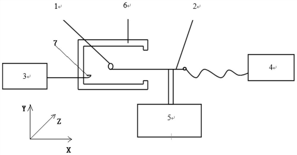
[0035] like figure 1 , a measuring device for obtaining the microwave magnetic field distribution of a microwave cavity, which is composed of a detection ring 1, a semi-rigid coaxial cable 2, a microwave source 3, a spectrum analyzer 4, a three-dimensional translation platform 5, and a microwave cavity 6 to be measured. The connection relationship of this device is: the semi-rigid coaxial cable 2 is electrically connected with the detection ring 1 and the spectrum analyzer 4 respectively. The constant power is fed into the microwave cavity 6 to be tested through the coupling ring 7 wound on the outer wall of the microwave cavity, and the microwave signal power P detected by the detection ring 1 through the semi-rigid coaxial cable 2 is read by the spectrum analyzer 4, and the microwave cavity 6 to be tested is Fixed by screws, by moving the three-dimensional translation stage 5 in the (X, Y, Z) direction, which is equivalent to moving the detection ring 1 in the (X, Y, Z) dire...


PUM


Abstract

The invention discloses a device for testing microwave field distribution in a microwave cavity, which is composed of a microwave source, a detection ring, a spectrum analyzer and a three-dimensional translation platform. The detection ring is made of one end of the semi-rigid coaxial cable SFT-50-1. The core wire of the semi-rigid coaxial cable is stripped and welded on the outer copper skin of the cable to form a circular detection ring, semi-rigid The other end of the coaxial cable is made into an SMA head, connected to the flexible coaxial cable through the SMA adapter, and then connected to the spectrum analyzer. The semi-rigid coaxial cable is fixed on the three-dimensional translation platform, and the invention moves the detection ring through the three-dimensional translation platform, and then uses a spectrum analyzer to read the microwave fields in various directions (X, Y, Z) in the microwave cavity detected in the detection ring Intensity, thus obtaining the distribution of the microwave field in the microwave cavity. This device has the characteristics of simple structure and convenient use, and can easily obtain the distribution of the field intensity in all directions of the microwave field.

Description

technical field [0001] The present invention relates to the field of testing microwave magnetic fields in microwave cavities, more specifically to a method for measuring the distribution of microwave magnetic fields in microwave cavities, and also to a device for measuring the distribution of microwave magnetic fields in microwave cavities, which is suitable for measuring microwave Microwave magnetic field distribution in all directions in the cavity. Background technique [0002] Rubidium atomic clocks are widely used in navigation, communication, electric power, transportation and other fields due to their small size, light weight, low power consumption, and high frequency stability. The core of the rubidium atomic clock is the physical and physical system. It is an atomic frequency discriminator, and the signal-to-noise ratio of its frequency discrimination signal directly determines the most important technical index of the rubidium atomic clock—frequency stability. [...

Claims


Application Information

Patent Timeline
Patent Type & Authority Patents(China)
IPC IPC(8): G01R33/032G01R33/02
CPCG01R33/02G01R33/0322
Inventor 梅刚华王芳赵峰明刚
Owner INNOVATION ACAD FOR PRECISION MEASUREMENT SCI & TECH CAS
Learn More