Wireless toilet cubicle indicating lamp

A kind of indicator light and wireless technology, which is applied in the field of wireless toilet position indicator light, can solve the problems of difficult wiring and unsightly appearance, and achieve the effect of alleviating the busy state, reducing the difficulty of wiring, and ensuring stability and accuracy

Pending Publication Date: 2019-09-17
广州通微物联科技有限公司
View PDF0 Cites 0 Cited by
  • Summary
  • Abstract
  • Description
  • Claims
  • Application Information

AI Technical Summary

Problems solved by technology

[0008] The input end of the induction signal is connected to the wireless squat position detection sensor through the wireless network, and the output end of the control signal is connected to the signal indicator through the LED control circuit. By aiming at the difficult and unsightly wiring of the toilet renovatio

Method used


Image

  • Wireless toilet cubicle indicating lamp
  • Wireless toilet cubicle indicating lamp
  • Wireless toilet cubicle indicating lamp

Examples


Embodiment 1

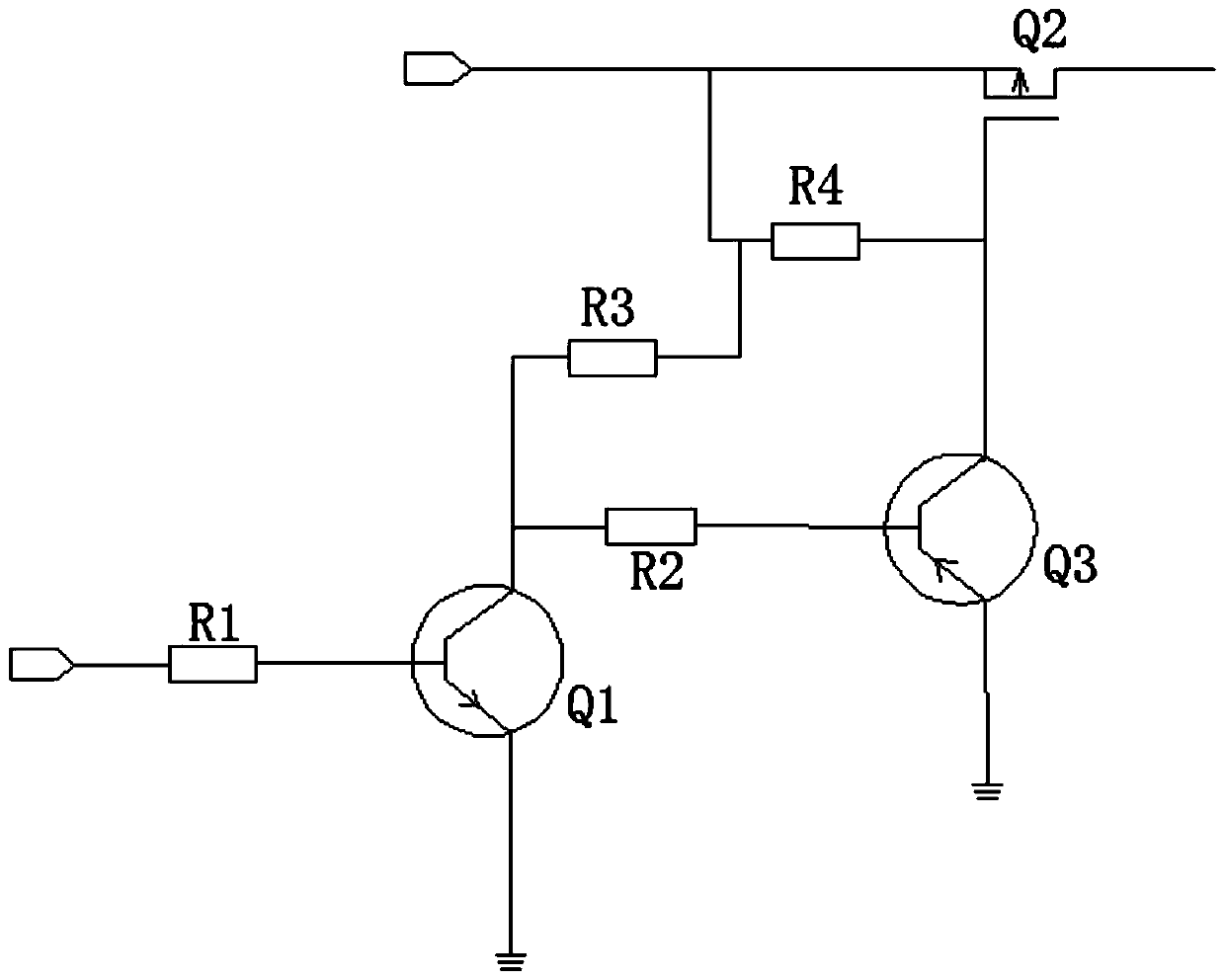
[0034] Such as figure 2 As shown, the control switch Q1 is an NPN triode, and the control switch Q3 is an NPN triode. When no one is in the toilet, the microprocessor receives the information through the wireless network and outputs a high level after learning the squatting state. At this time, the control The switch Q1 is turned on, the base of the PNP transistor Q3 is turned on at a low level, the MOS tube Q2 is turned on, the drain outputs 5V, and the green light is on, otherwise, the microprocessor outputs a low level, the control switch Q1 is turned off, and the base of the PNP transistor Q3 Low level, cut off, at this time, the MOS tube Q2 is cut off, and the green light is off.

Embodiment 2

[0036] Such as image 3 As shown, the control switch Q1 is an NPN triode, and the control switch Q3 is a PNP triode. The principle is consistent with that of Embodiment 1. When the microprocessor outputs a low level, the control switch Q1 is turned off, the control switch Q3 is turned on, and the red light is on. , otherwise, the red light goes out, which are all within the protection scope of the present invention.

Embodiment 3

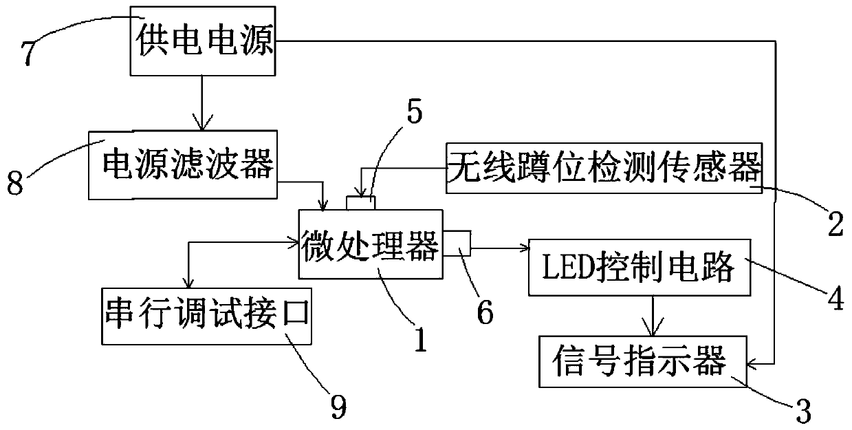
[0038] Such as Figure 4 As shown, the wireless squatting sensor actively sends the detected squatting status to the wireless host, and the wireless host sends a response message to the wireless squatting sensor after receiving the information. In the case of no response message is received, the wireless squat position sensor will repeat the sending operation until it receives a response message before stopping this transmission. That is, the wireless indicator light cannot obtain the status of the squatting position during the entire communication process. The existing technology is to send a message to the wireless indicator light after sending a signal to the host through the wireless squatting sensor. Or the wireless host sends a message to the wireless indicator light after receiving the information from the wireless squat sensor. This will greatly increase the busyness of the wireless network. But when the network is busy, the stability of wireless communication will ...


PUM


Abstract

The invention relates to the technical field of Internet of Things monitoring, in particular to a wireless toilet cubicle indicating lamp, which comprises a microprocessor, a wireless squatting position detection sensor and a signal indicator, and further comprises an LED control circuit, wherein an induction signal input end and a control signal output end are arranged on the microprocessor; the induction signal input end communicates with the wireless squatting position detection sensor through a wireless network, and the control signal output end is connected to the signal indicator through the LED control circuit. According to the wireless toilet cubicle indicating lamp disclosed by the invention, a wireless communication mode is adopted for a situation that a toilet is difficult to remodel and is not attractive, and the level output by the sensor in the toilet is adjusted through the LED control circuit, so that an electric signal is converted to control the working condition of the signal indicator, and thus the condition in the toilet can be conveniently judged, and simplicity and convenience are achieved.

Description

technical field [0001] The invention relates to the technical field of Internet of Things monitoring, and more specifically, to a wireless toilet position indicator light. Background technique [0002] At present, in major tourist attractions and large office buildings, the problem of queuing at the entrance of public toilets still exists, especially at the entrance of women's toilets. The queuing situation is still serious, so reasonable drainage is particularly important. [0003] At present, there are not many products on the market for this solution. When the public toilet door is closed, people do not know whether there is anyone in the public toilet. Generally speaking, it is necessary to detect whether there is a person in the toilet. It is very difficult to renovate the built public toilets. Therefore, the simple installation method is an important problem, which leads to another problem. In the case of no wiring, data transmission needs further technical solutions. ...

Claims


Application Information

Patent Timeline
IPC IPC(8): G08B5/36
CPCG08B5/36
Inventor 蔡成想
Owner 广州通微物联科技有限公司
Why Eureka
Try Eureka