An automatic nailing and nailing machine

A nailing and nailing machine technology, which is applied in the field of automatic nailing and nailing machines, can solve the problems of low nailing efficiency, high nailing difficulty, and low efficiency, and achieve the effect of improving nailing efficiency and saving labor costs

Active Publication Date: 2021-05-25
HUAWAY IOT TECH
View PDF7 Cites 0 Cited by
  • Summary
  • Abstract
  • Description
  • Claims
  • Application Information

AI Technical Summary

Problems solved by technology

[0002] When the existing pneumatic nail gun or electric nail gun is in use, it is necessary to forcefully push the nail against the object to be nailed, otherwise the nail cannot be completely inserted. After firing, the reaction force of the nail gun reaches the hand, and the strength of the hand is easy Pushing the nail gun to the object to be nailed will easily form a pit where the gun head hits the nailed object, and the existing pneumatic nail gun or electric nail gun drives one nail at a time, and the nailing efficiency is low
In addition, after a row of nails is finished, it is necessary to manually add nails, which is labor-intensive and time-consuming. When the row of nails is broken, it is difficult to add nails, and the individual nails that are broken are often discarded, resulting in a waste of resources.
[0003] The patent application No. 201721025281.1 discloses a wall brick structure with a nail frame on the vertical surface. The wall bricks used for building walls are easy to hang the mortar so that the mortar on the vertical surface of the wall brick does not fall. Steel nails are driven in rows. The efficiency of the existing nail guns for driving steel nails on brick surfaces is low, and manual nailing is difficult to control.

Method used


Image

  • An automatic nailing and nailing machine
  • An automatic nailing and nailing machine
  • An automatic nailing and nailing machine

Examples


Embodiment Construction

[0030]The technical solutions of the present invention will be better understood by those skilled in the art, and the present invention will be described in more detail below with reference to the accompanying drawings and specific embodiments.

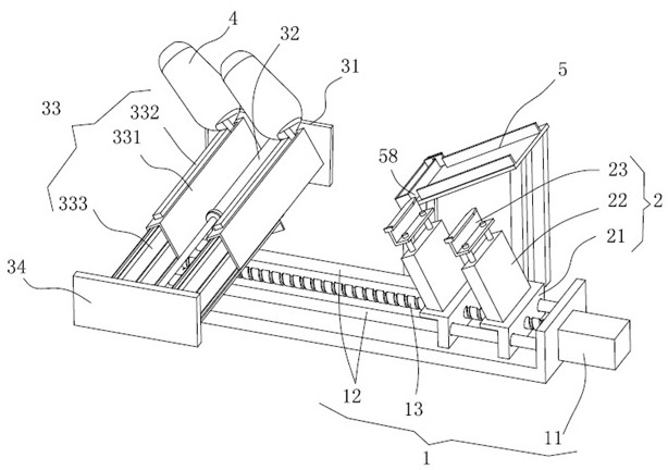
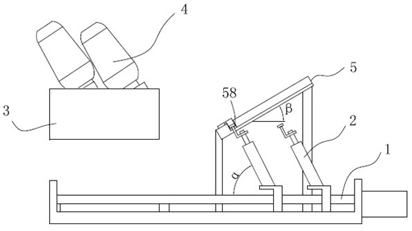
[0031]Such asfigure 1 ,figure 2 As shown, the present invention discloses an automatic actuated nailing machine, including control assembly (not shown), transverse mode group 1, reserve assembly 5, several nailing assembly 2, gun assembly 3 and several Run head 4. Control components and transverse modules 1, nail assembly 2, gun assembly 3, gun head 4, reserve assembly, control transverse shift module 1, nail assembly 2, gun assembly 3, gun head 4, The action of the nail assembly 5. In the figure of the present embodiment, only two sets of nailing assemblies 2, only two sets of guns 33, two sets of gun heads 4, and actually use multiple sets as needed, easy to use multiple sets of row 6 as needed At the same time, it is played, and the emergen...


PUM


Abstract

The invention discloses an automatic nailing and nailing machine, which comprises a control assembly, a nail feeding assembly, a gun chamber assembly and several gun heads; the nail feeding assembly includes a first push rod and a nail frame, and the nail frame is fixed on the first push rod At the end of the rod, the nail frame is made of non-ferrous materials; the chamber assembly includes a fixed frame, a second push rod, a number of chambers and connecting plates, and the chamber includes a nail frame, an electromagnet installed on the nail frame and an electromagnet installed on the nail frame. The elastic push plate in the nail frame, the nail frame is located above the nail frame and connected with the fixed frame, the end of the nail frame is equipped with a gun head, the end of the gun head is provided with a nail outlet, the electromagnet is located above the nail frame, and the elastic push plate is fixed on the On the connection plate, one end of the second push rod is connected with the fixed frame, and the other end is connected with the connection plate, and the second push rod controls the movement of the connection plate to drive the elastic push plate to move in the nail frame. The present invention realizes automatic batch adding of nails through magnetic adsorption, realizes automatic nailing and nailing, improves efficiency, and avoids waste caused by disconnection of row nails in the manual nailing process.

Description

Technical field[0001]The present invention relates to a nailing machine, especially an automatic fetch nailing machine.Background technique[0002]When the existing pneumatic nail gun or electric spike gun is in use, you need to use the top of your hand to make a nail, otherwise the nail cannot be completely entered, after launch, the reaction force of the nail gun is in the hands, the power of the hand is easy Push the spikes to the nails, easily form a pit on the nail, and the existing pneumatic nail gun or electric spike gun is a nail, the nail efficiency is low. And after a row is finished, it needs to be handmade. When the cost is consumed, when the routine is broken, the difficulty is difficult, and the disconnected individual steel nails are often discarded, resulting in waste of resources.[0003]The patent of the application No. 201721025281.1 discloses a wall tile structure of a vertical surface, a wall brick for building walls, in order to facilitate flush, so that the mortar...

Claims


Application Information

Patent Timeline
Patent Type & Authority Patents(China)
IPC IPC(8): B27F7/26B27F7/36B27F7/38
CPCB27F7/26B27F7/36B27F7/38
Inventor 刘昌臻陈思鑫
Owner HUAWAY IOT TECH
Why Eureka
Try Eureka