Nail gun with automatic nail supply device

A nailing gun and feeding device technology, applied in the field of nailing guns, can solve the problems of low degree of automation, low nailing efficiency, low practicability, etc., to improve nailing efficiency, increase storage capacity, and simple overall structure Effect

Pending Publication Date: 2018-03-23
彭方
View PDF15 Cites 1 Cited by
  • Summary
  • Abstract
  • Description
  • Claims
  • Application Information

AI Technical Summary

Problems solved by technology

The blank bullets that fire nails are different from ordinary military blank bullets only in size, and they also have harmful effects on people. The nail gun used for nail fastening technology is an advanced modern fastening technology, which is different from traditional Compared with traditional pre-embedded fixation, hole pouring, bolt connection, welding and other methods, it has many advantages. It has its own energy, thus getting rid of the burden of wires and air ducts, facilitating on-site and high-altitude operations, fast operation, and short construction period. It can greatly reduce the labor intensity of workers, and the function is reliable and safe. It can even solve some construction problems that were difficult to solve in the past, save money, and reduce construction costs. At present, the raw materials of many nail guns are made by juxtaposing the nail plate structure. It is installed in the magazine of the nailing gun, so as to realize the continuous automatic nailing process. However, at present, the nail plates of many nailing guns need to be installed manually, so the degree of automation is not high, the efficiency of nailing is low, and it is a waste of manpower, so it is practical not tall

Method used


Image

  • Nail gun with automatic nail supply device
  • Nail gun with automatic nail supply device
  • Nail gun with automatic nail supply device

Examples


Embodiment Construction

[0022] The following will clearly and completely describe the technical solutions in the embodiments of the present invention. Obviously, the described embodiments are only some of the embodiments of the present invention, rather than all the embodiments. Based on the embodiments of the present invention, all other embodiments obtained by persons of ordinary skill in the art without creative work fall within the protection scope of the present invention:

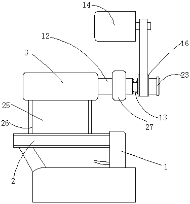
[0023] Such as Figure 1 to Figure 3 A nailing gun with an automatic feeding device is shown, including a nailing gun, a clip feeding device, a feeding device and a transmission device, and the nailing gun includes a gun body 1 and a main magazine 2 for placing nail plates After the nail plate is placed in the main magazine, the nailing process is realized through the power device on the gun body.

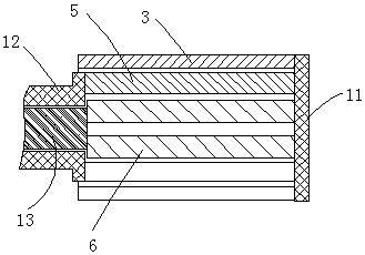
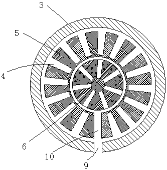
[0024] The clip feeding device includes a plurality of magazine barrels and a fixed shell 3, and a plurality of the clip barre...


PUM


Abstract

The invention discloses a nail gun with an automatic nail supply device. The nail gun comprises a nail gun body, a clip feeding device, a conveying device and a transmission device. The nail gun bodycomprises a gun body and a main nail bin for containing nail plates. The clip feeding device comprises a plurality of clip barrels and a fixed shell, and the multiple clip barrels are each arranged tobe of a hollow barrel-shaped structure, are sequentially fixed to each other in a sleeved mode from inside to outside and are coaxially arranged; each clip barrel is internally provided with a plurality of branched nail bins for containing the nail plates; the multiple clip barrels are driven by the transmission device and freely rotate relatively; the clip barrels are arranged in the fixed shell, the lower portion of the shell is provided with a first discharging outlet, and the clip barrels are provided with second discharging outlets matched with the first discharging outlet; and the nailplates flow out from the discharging outlets and are conveyed into the main nail bin through the conveying device. Through the nail gun with the automatic nail supply device, the storage quantity of the nail plates is increased to a great extent, the continuous nailing sustainability of the nail gun is improved, the nailing efficiency is improved, and the practicality is high.

Description

Technical field: [0001] The invention relates to a nail gun with an automatic bomb feeding device, and relates to the technical field of nail guns. Background technique: [0002] Nail gun, also known as nail gun, is often called a nail gun because its shape and principle are similar to pistols. It uses the gunpowder gas generated by firing blank bullets as power to drive nails into buildings. The blank bullets that fire nails are different from ordinary military blank bullets only in size, and they also have harmful effects on people. The nail gun used for nail fastening technology is an advanced modern fastening technology, which is different from traditional Compared with traditional pre-embedded fixation, hole pouring, bolt connection, welding and other methods, it has many advantages, and it has its own energy, thus getting rid of the burden of wires and air ducts, facilitating on-site and high-altitude operations, fast operation, and short construction period. It can g...

Claims


Application Information

Patent Timeline
Patent Type & Authority Applications(China)
IPC IPC(8): B25C1/00B25C1/10B25C7/00
CPCB25C1/001B25C1/10B25C7/00
Inventor 彭方
Owner 彭方
Why Eureka
Try Eureka