Rapid screw driving device for plate product packaging

A technology for driving screws and products, used in manufacturing tools, nailing tools, nailing tools, etc., can solve the problems of low nailing efficiency, labor force, slow speed, etc., to reduce manual operation steps and meet the needs of use. demand, the effect of improving usability

Pending Publication Date: 2021-03-16
FOSHAN CHUANGLIBAO PACKAGING MACHINERY
View PDF9 Cites 1 Cited by
  • Summary
  • Abstract
  • Description
  • Claims
  • Application Information

AI Technical Summary

Problems solved by technology

[0002] In the packaging process, utensils made of wooden boards are usually used to load materials. Traditional wooden board assembly is inefficient. Most workers assemble and transfer at fixed points, which requires more labor and is not conducive to production and packaging. Therefore, at this stage Most of the plate products are spliced ​​together by screws, which is convenient and fast for packaging
[0003] However, at this stage, the screwing device used to ensure the use of board products, such as the fast screwing device for board product packaging with application number 201810263389.7, includes a conveyor belt for loading wooden packaging boxes, and a support rod is arranged above the conveyor belt. And a sliding sleeve is provided on the support rod, and the sliding sleeve is displaced left and right on the support rod, and a screw gun is arranged on the sliding sleeve; although it realizes the screw assembly of the board product, it is in the process of using In the middle, the function is simple, and the staff still needs to drive the screws manually, and at the same time, the nailing efficiency is low and the speed is slow, and only one set of screws can be driven in at a time.

Method used


Image

  • Rapid screw driving device for plate product packaging
  • Rapid screw driving device for plate product packaging
  • Rapid screw driving device for plate product packaging

Examples


Embodiment Construction

[0021] The following will clearly and completely describe the technical solutions in the embodiments of the present invention with reference to the accompanying drawings in the embodiments of the present invention. Obviously, the described embodiments are only some, not all, embodiments of the present invention. Based on the embodiments of the present invention, all other embodiments obtained by persons of ordinary skill in the art without making creative efforts belong to the protection scope of the present invention.

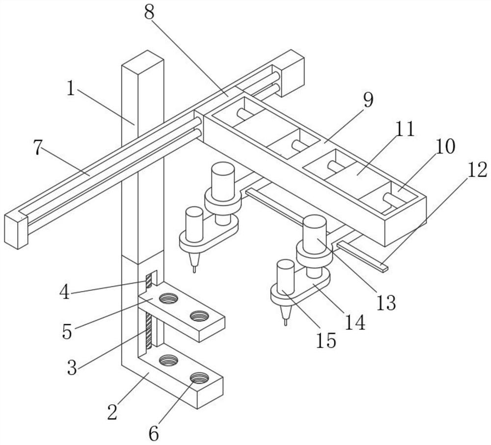
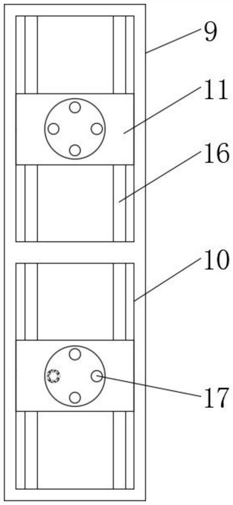
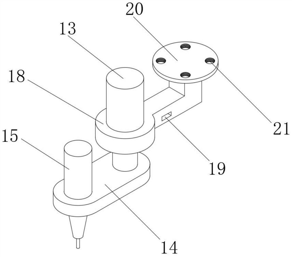
[0022] The present invention provides such Figure 1-4 A fast screwing device for board product packaging shown includes a supporting side bar 1, a fixed clamp bar 2, an electric slide rail 7 and a side support bar 9. The fixed clamp bar 2 has an L-shaped structure, and the fixed clamp bar 2 The inner side of the vertical part is provided with a side groove 3, and a lead screw 4 is installed in the side groove 3, and a pressure rod 5 is arranged on the upper e...


PUM


Abstract

The invention discloses a rapid screw driving device for plate product packaging. The rapid screw driving device for plate product packaging comprises a supporting lateral rod, a fixing clamp rod, anelectric sliding rail and a lateral support rod, wherein the fixing clamp rod is of an L-shaped structure; a lateral groove is formed in the inner side surface of the vertical part of the fixing clamprod; a lead screw is arranged in the lateral groove; a press rod is arranged at the upper end of the horizontal part of the fixing clamp rod; one end of the press rod extends into the lateral grooveand is sleeved on the lead screw through screw threads; the supporting lateral rod is welded and fixed to the top end of the vertical part of the fixing clamp rod; the electric sliding rail is fixed at the upper end of the side surface, facing the press rod, of the supporting lateral rod; and a sliding plate glidingly connected with the electric sliding rail is arranged on the electric sliding rail. The rapid screw driving device for plate product packaging has the advantages that two-side screw driving can be performed on a plate product on a conveying device at the same time; screw driving is faster; and screw driving position movement and screw driving height adjustment can be achieved by the electric sliding rail and electric push rods, so that different use requirements are met.

Description

technical field [0001] The invention belongs to the technical field of board product packaging, and in particular relates to a fast screwing device for board product packaging. Background technique [0002] During the packaging process, utensils made of wooden boards are usually used to load materials. Traditional wooden board assembly is inefficient. Most workers assemble and transfer at fixed points, which requires more labor and is not conducive to production and packaging. Therefore, at this stage Most of the board products are spliced ​​together by screws, which is convenient and fast for packaging. [0003] However, at this stage, the screwing device used to ensure the use of board products, such as the fast screwing device for board product packaging with the application number 201810263389.7, includes a conveyor belt for loading wooden packaging boxes, and a support rod is arranged above the conveyor belt. And a sliding sleeve is provided on the support rod, and the...

Claims


Application Information

Patent Timeline
Patent Type & Authority Applications(China)
IPC IPC(8): B27F7/02B27M3/34B27M3/00
CPCB27F7/02B27M3/34B27M3/0073
Inventor 陈小梅郭敏衡
Owner FOSHAN CHUANGLIBAO PACKAGING MACHINERY
Why Eureka
Try Eureka