Automatic nail feed nailing machine

A nailing and nailing machine technology, applied in the field of automatic nailing and nailing machines, can solve the problems of high nailing difficulty, low nailing efficiency, waste of resources, etc., and achieve the effect of saving labor costs and improving nailing efficiency.

Active Publication Date: 2019-09-20
HUAWAY IOT TECH
View PDF7 Cites 3 Cited by
  • Summary
  • Abstract
  • Description
  • Claims
  • Application Information

AI Technical Summary

Problems solved by technology

[0002] When the existing pneumatic nail gun or electric nail gun is in use, it is necessary to forcefully push the nail against the object to be nailed, otherwise the nail cannot be completely inserted. After firing, the reaction force of the nail gun reaches the hand, and the strength of the hand is easy Pushing the nail gun to the object to be nailed will easily form a pit where the gun head hits the nailed object, and the existing pneumatic nail gun or electric nail gun drives one nail at a time, and the nailing efficiency is low
In addition, after a row of nails is finished, it is necessary to manually add nails, which is labor-intensive and time-consuming. When the row of nails is broken, it is difficult to add nails, and the individual nails that are broken are often discarded, resulting in a waste of resources.
[0003] The patent application No. 201721025281.1 discloses a wall brick structure with a nail frame on the vertical surface. The wall bricks used for building walls are easy to hang the mortar so that the mortar on the vertical surface of the wall brick does not fall. Steel nails are driven in rows. The efficiency of the existing nail guns for driving steel nails on brick surfaces is low, and manual nailing is difficult to control.

Method used


Image

  • Automatic nail feed nailing machine
  • Automatic nail feed nailing machine
  • Automatic nail feed nailing machine

Examples


Embodiment Construction

[0030] In order to enable those skilled in the art to better understand the technical solutions of the present invention, the present invention will be described in further detail below in conjunction with the accompanying drawings and specific embodiments.

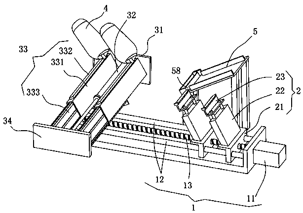
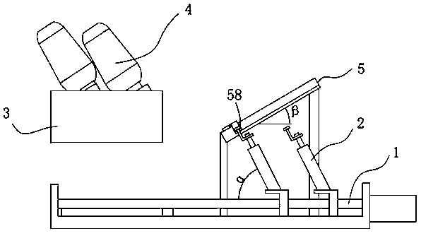
[0031] Such as figure 1 , figure 2 As shown, the present invention discloses an automatic nailing and nailing machine, including a control assembly (not shown in the figure), a traverse module 1, a nail storage assembly 5, several nail feeding assemblies 2, a chamber assembly 3 and several Gun head 4. The control component is connected with the traverse module 1, the nail feeding component 2, the gun bore component 3, the gun head 4, and the nail storage component, and controls the traverse module 1, the nail feeding component 2, the gun bore component 3, the gun head 4, Actions of the nail storage assembly 5. Only two groups of nail feeding assemblies 2 are shown in the figure of this embodiment, and only two groups ...


PUM


Abstract

The invention discloses an automatic nail feed nailing machine which comprises a control component, nail delivery components, a chamber component and a plurality of gun heads, wherein the nail delivery components comprise first push rods and nail racks; the nail racks are fixed at the end parts of the first push rods; the nail racks are made from nonferrous materials; the chamber component comprises a fixing rack, a second push rod, a plurality of chambers and a connecting plate; the chambers comprise nail frames, electromagnets mounted on the nail frames and elastic push plates mounted in the nail frames; the nail frames are located above the nail racks and connected with the fixing rack; the gun heads are mounted at the end parts of the nail frames; nail outlet grooves are formed at the end parts of the gun heads; the electromagnets are located above the nail frames; the elastic push plates are fixed on the connecting plate; one end of the second push rod is connected with the fixing rack; the other end of the second push rod is connected with the connecting plate; and the second push rod controls the connecting plate to move to drive the elastic push plates to move in the nail frames. Automatic massive nail feed is achieved in a magnetic adsorption manner; the automatic nail feed and nailing are achieved; the efficiency is improved; and the waste due to breaking of strip nails in a manual nail feed process is avoided.

Description

technical field [0001] The invention relates to a nailing machine, in particular to an automatic nailing and nailing machine. Background technique [0002] When the existing pneumatic nail gun or electric nail gun is in use, it is necessary to forcefully push the nail against the object to be nailed, otherwise the nail cannot be completely inserted. After firing, the reaction force of the nail gun reaches the hand, and the strength of the hand is easy When the nail gun is pushed onto the object to be nailed, it is easy to form a pit where the head of the gun hits the nailed object, and the existing pneumatic nail gun or electric nail gun drives one nail at a time, and the nailing efficiency is low. Moreover, after a row of nails is finished, manual nailing is required, which is labor-intensive and time-consuming. When the row of nails is disconnected, it is difficult to add nails, and individual steel nails that are disconnected are often discarded, resulting in a waste of r...

Claims


Application Information

Patent Timeline
Patent Type & Authority Applications(China)
IPC IPC(8): B27F7/26B27F7/36B27F7/38
CPCB27F7/26B27F7/36B27F7/38
Inventor 刘昌臻陈思鑫
Owner HUAWAY IOT TECH
Why Eureka
Try Eureka