elevator

A technology of elevators and electromagnetic columns, applied in the field of elevators, can solve the problems of uneven force on the traction rope, affecting the maximum load capacity of the car, wear and tear of the traction rope and the car, etc.

Active Publication Date: 2021-02-05
烟台祥润电梯有限公司
View PDF5 Cites 3 Cited by
  • Summary
  • Abstract
  • Description
  • Claims
  • Application Information

AI Technical Summary

Problems solved by technology

[0002] Elevator is a necessary vehicle for high-rise buildings at present. According to the driving mode, elevators can be divided into traction drive and hydraulic drive. Among them, traction drive has many advantages such as safety and reliability, unlimited lifting height, and easy control of elevator speed. , so the traction-driven elevator has gradually become the mainstream of elevator products; the traction-driven elevator includes a car, a traction system and a counterweight system, and the car is lifted and lowered by traction ropes and traction machines. Connected to the top of the car, the direction of the traction resultant force of the traction rope passes through the center of gravity of the car, so as to ensure that the car can rise and fall smoothly; but in actual use, passengers will not be evenly distributed in the car , the position of the center of gravity of the car shifts; this situation easily causes uneven force on each traction rope, making one of the traction ropes reach the traction limit, and the car alarm sounds; however, there are still There is a lot of space, but the elevator will not run normally; this situation will easily lead to unstable operation of the car, and more likely to cause wear and tear on the traction rope and the car, posing a greater safety hazard; at the same time, it will affect the maximum carrying capacity of the car. Congestion of upstairs and downstairs during peak hours of flow of people

Method used


Image

  • elevator
  • elevator
  • elevator

Examples


Embodiment

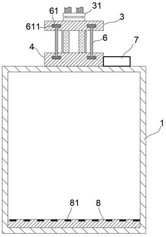
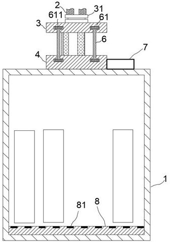
[0019] exist Figure 1 to Figure 5 In the illustrated embodiment, the elevator includes a car 1, slide rails, a traction machine, a traction rope 2 and a counterweight structure; the traction rope 2 is powered by the traction machine, and the two ends of the traction rope 2 are respectively Connected to the top of the car 1 and the counterweight structure; the car 1 and the counterweight structure are respectively slid and set on their respective slide rails;

[0020] The car 1 and the traction rope 2 are connected through an adjusting device;

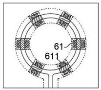
[0021] The adjustment device includes an upper support plate 3 and a lower support plate 4, the lower support plate 4 is fixedly arranged in the center of the roof of the car 1, and the upper support plate 3 is tightly connected with the traction rope 2; The support plate 3 and the traction rope 2 are connected by an adjustment disc 31; the adjustment disc 31 includes two parallel discs and a connecting shaft, and the two discs are re...


PUM


Abstract

The invention relates to an elevator, comprising a car, a slide rail, a traction machine, a traction rope and a counterweight structure; the car and the traction rope are connected through an adjustment device; the adjustment device includes an upper support plate and a lower There are adjustment chute on the opposite surface of the upper support plate and the lower support plate, the upper support plate and the lower support plate are connected by adjusting rods, and the sliding heads at both ends of each adjusting rod are slidably set on the upper support plate , in the adjustment chute on the lower support plate; the electromagnetic column is embedded in the sliding head; in the same adjustment chute, the magnetic force of the electromagnetic column in the adjacent sliding head repels each other; on the inner bottom surface of the car There are pedals, and pressure-sensitive sheets are arranged in an equidistant array on the surface of the pedals; the elevator has a novel structure and a unique principle, and can intelligently adjust the pulling position of the traction rope according to the distribution of passengers in the car, thereby Ensure that the traction ropes are evenly stressed, promote the smooth lifting of the car, and effectively improve the safety and work efficiency of the elevator.

Description

technical field [0001] The invention relates to a lifting and carrying mechanism, in particular to an elevator. Background technique [0002] Elevator is a necessary vehicle for high-rise buildings at present. According to the driving mode, elevators can be divided into traction drive and hydraulic drive. Among them, traction drive has many advantages such as safety and reliability, unlimited lifting height, and easy control of elevator speed. , so the traction-driven elevator has gradually become the mainstream of elevator products; the traction-driven elevator includes a car, a traction system and a counterweight system, and the car is lifted and lowered by traction ropes and traction machines. Connected to the top of the car, the direction of the traction resultant force of the traction rope passes through the center of gravity of the car, so as to ensure that the car can rise and fall smoothly; but in actual use, passengers will not be evenly distributed in the car , th...

Claims


Application Information

Patent Timeline
Patent Type & Authority Patents(China)
IPC IPC(8): B66B7/10B66B1/34
CPCB66B1/3484B66B7/10
Inventor 李聪
Owner 烟台祥润电梯有限公司
Why Eureka
Try Eureka