Refuse landfill leachate guiding and discharging pipe dredging device

A technology for landfill and leachate

Active Publication Date: 2019-09-20
中山市恒辉自动化科技有限公司
View PDF12 Cites 1 Cited by
  • Summary
  • Abstract
  • Description
  • Claims
  • Application Information

AI Technical Summary

Problems solved by technology

The leachate is collected at the bottom of the landfill by gravity. There is a leachate drainage pipe at the bottom of the landfill. The pipeline is a flower pipe, and the leachate flows into the pipe from the flower hole on the flower pipe. , the flower hole on the flower tube is blocked, using liquid recoil is one of the ways to clear the flower hole, but the position of the liquid spray pipe on the liquid distribution pipe used for recoil is fixed, and the recoil range is limited. By increasing the liquid spray pipe The number method not only increases the production cost, but also because the liquid flow rate is constant, after increasing the number of liquid spray pipes, the impact force of the sprayed liquid becomes smaller, resulting in a decrease in the dredging effect. The length of the tube is long, and it is difficult to reinsert

Method used


Image

  • Refuse landfill leachate guiding and discharging pipe dredging device
  • Refuse landfill leachate guiding and discharging pipe dredging device
  • Refuse landfill leachate guiding and discharging pipe dredging device

Examples


Embodiment Construction

[0024] In order to make the technical means, creative features, goals and effects achieved by the present invention easy to understand, the present invention will be further described below in conjunction with specific embodiments.

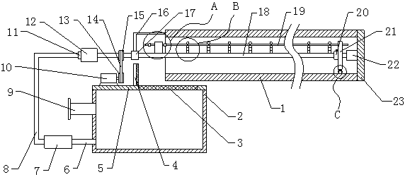
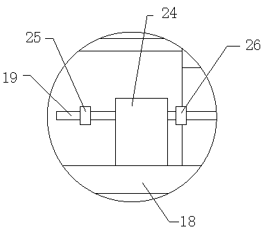
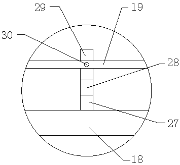
[0025] see Figure 1 to Figure 8 , the present invention provides a technical solution: a dredging device for leachate guide and drainage pipes in landfill sites, including a flower tube 1, a cover 23 is installed on the right end of the flower tube 1, and the cover 23 realizes the sealing of one end of the flower tube 1 Blocking, the middle part of the left end face of the cover 23 is equipped with a limit cylinder 22, and the liquid distribution pipe 18 is installed in the limit cylinder 22, and the outer surface of the left end of the liquid distribution pipe 18 is sleeved with a rolling bearing 17, and the rolling bearing 17 is arranged on the left side of the flower tube 1. And the outer surface of rolling bearing 17 is fixed pole 16, and the...


PUM


Abstract

The invention provides a refuse landfill leachate guiding and discharging pipe dredging device. The refuse landfill leachate guiding and discharging pipe dredging device comprises a floral pipe; a sealing cover is mounted on the right end surface of the floral pipe, a limiting cylinder is installed at the middle position of the left end surface of the sealing cover, the limiting cylinder is internally provided with a liquid distributing pipe, and a first rolling bearing is arranged on the outer surface of the left side of the liquid distributing pipe in a sleeved mode; a waste liquid pool is disposed on the lower left side of the floral pipe, a mounting cover plate is disposed at the middle position of the upper end surface of the waste liquid pool, a driving motor is installed on the left side of the upper end surface of the cover plate, a connecting pipe is installed on the lower side of the left end surface of the waste liquid pool, a water inlet end of a water pump is connected to the other end of the connecting pipe, a liquid conveying pipe is installed at the water outlet end of the water pump, and a cylinder is fixed to the outer surface of the left end of the liquid distributing pipe; and a liquid spraying assembly is mounted on the annular side surface of the liquid distributing pipe, and a support assembly is mounted on the outer surface of the right end of the liquid distributing pipe. Compared with the prior art, the refuse landfill leachate guiding and discharging pipe dredging device has the following beneficial effects that the liquid spraying range is expanded, and the difficulty of disassembling and assembling of the liquid distributing pipe is lowered.

Description

technical field [0001] The invention relates to a device for dredging a leachate guide and drain pipe of a landfill site, and belongs to the field of landfill treatment equipment. Background technique [0002] Garbage landfills are mainly carried out in landfills. When the waste piles in the landfill degrade, landfill gas and a large amount of leachate will be produced. The leachate is collected at the bottom of the landfill by gravity. There is a leachate drainage pipe at the bottom of the landfill. The pipeline is a flower pipe, and the leachate flows into the pipe from the flower hole on the flower pipe. , the flower hole on the flower tube is blocked, using liquid recoil is one of the ways to clear the flower hole, but the position of the liquid spray pipe on the liquid distribution pipe used for recoil is fixed, and the recoil range is limited. By increasing the liquid spray pipe The number method not only increases the production cost, but also because the liquid flow...

Claims


Application Information

Patent Timeline
Patent Type & Authority Applications(China)
IPC IPC(8): E03F1/00E03F3/00E03F7/00
CPCE03F1/00E03F3/00E03F7/00
Inventor 杨军科丁党来代恒科
Owner 中山市恒辉自动化科技有限公司
Why Eureka
Try Eureka