Camera lifting device and mobile terminal

A lifting device and camera technology, applied in image communication, TV, machine/bracket, etc., can solve the problems of low transmission efficiency, achieve high transmission efficiency, ensure installation stability, and reduce installation difficulty

Inactive Publication Date: 2019-09-20
GOERTEK INC
View PDF6 Cites 6 Cited by
  • Summary
  • Abstract
  • Description
  • Claims
  • Application Information

AI Technical Summary

Problems solved by technology

[0004] The main purpose of the present invention is to provide a camera lifting device and a mobile terminal, aiming to solve the problem of low transmission efficiency existing in the lifting camera

Method used


Image

  • Camera lifting device and mobile terminal
  • Camera lifting device and mobile terminal
  • Camera lifting device and mobile terminal

Examples


Embodiment Construction

[0026] The following will clearly and completely describe the technical solutions in the embodiments of the present invention with reference to the accompanying drawings in the embodiments of the present invention. Obviously, the described embodiments are only part of the embodiments of the present invention, not all of them. Based on the embodiments of the present invention, all other embodiments obtained by persons of ordinary skill in the art without creative efforts fall within the protection scope of the present invention.

[0027] It should be noted that all directional indications (such as up, down, left, right, front, back...) in the embodiments of the present invention are only used to explain the relationship between the components in a certain posture (as shown in the accompanying drawings). Relative positional relationship, movement conditions, etc., if the specific posture changes, the directional indication will also change accordingly.

[0028] In addition, in t...


PUM


Abstract

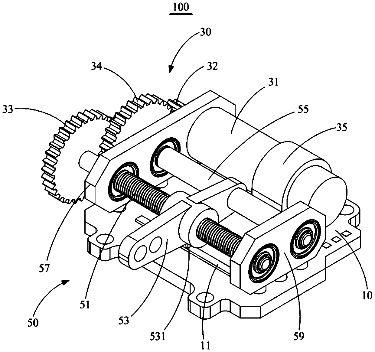
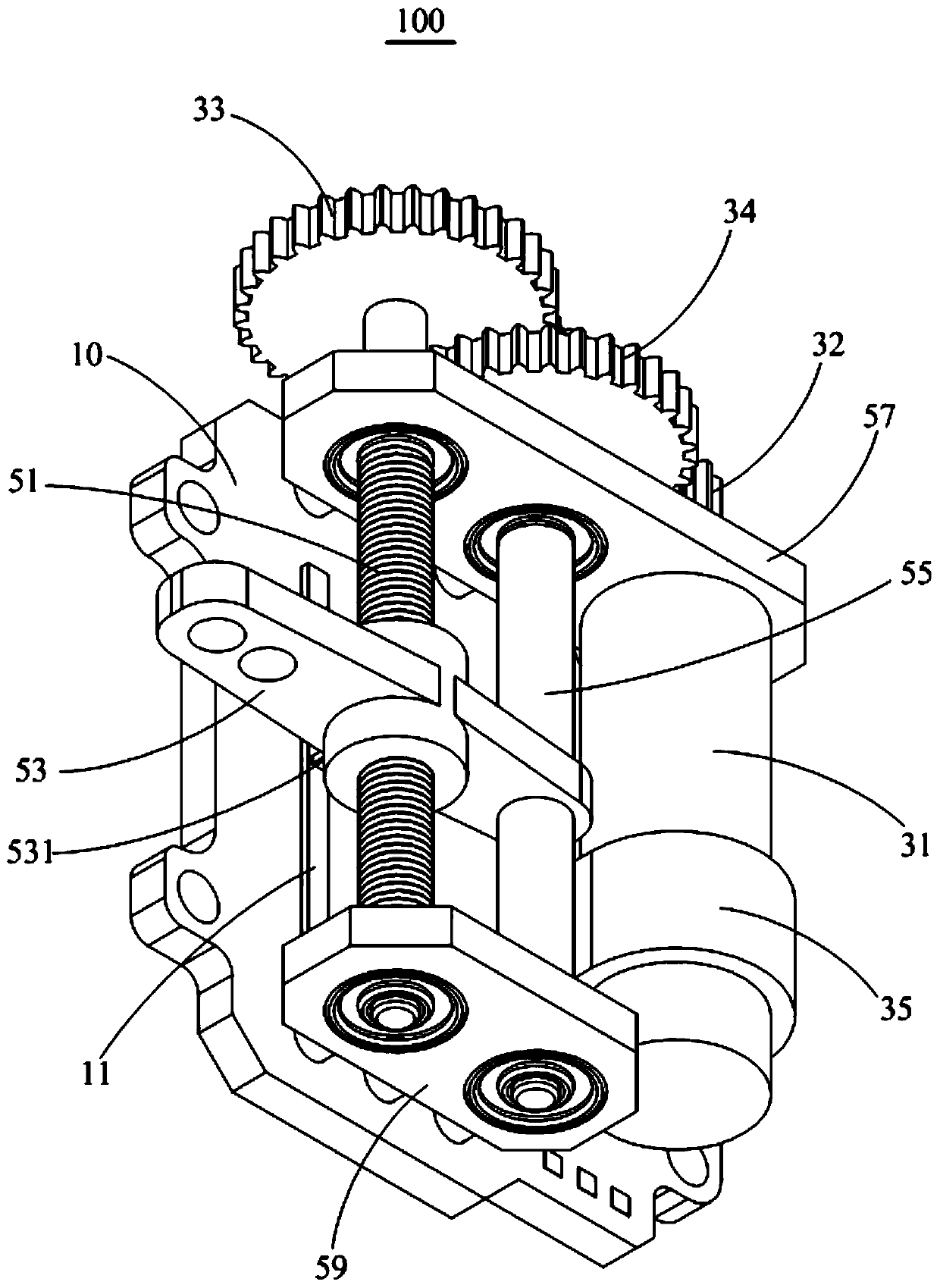
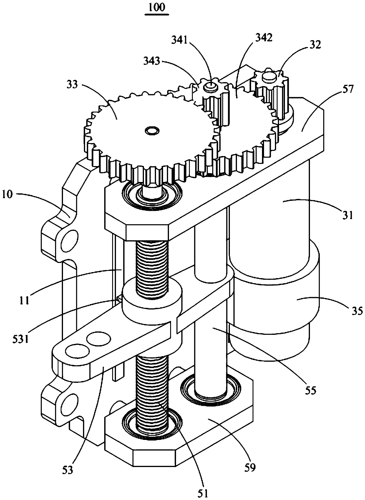
The invention discloses a camera lifting device and a mobile terminal applying the camera lifting device. The camera lifting device comprises an installation plate, a drive mechanism and a lifting mechanism, wherein the drive mechanism is arranged on the surface of the installation plate; and the lifting mechanism is arranged on the surface, facing the drive mechanism, of the installation plate, is in transmission connection with the drive mechanism, and is used for installing a camera; and the drive mechanism drives the lifting mechanism to run so as to enable the camera to lift up or go down. According to the technical scheme provided by the invention, the problem of low transmission efficiency of an existing lifting camera can be solved.

Description

technical field [0001] The invention relates to the technical field of mobile terminals, in particular to a camera lifting device and a mobile terminal using the camera lifting device. Background technique [0002] At present, the mobile terminal with a lifting camera has a camera hidden behind the display screen of the mobile terminal when not in use, and protrudes out of the display screen when in use. This type of mobile terminal has a high screen-to-body ratio and is very popular among users. The mobile terminal of the existing lifting camera generally uses a combination of components such as a stepping motor, a micro-gearbox, and a lead screw to realize the lifting movement of the camera. During assembly, these components are generally supported and fixed in different structures. This assembly method often has the problem of low transmission efficiency. [0003] The above content is only used to assist in understanding the technical solution of the present invention, a...

Claims


Application Information

Patent Timeline
Patent Type & Authority Applications(China)
IPC IPC(8): F16M11/18F16M11/04H04N5/225
CPCF16M11/18F16M11/046H04N23/00
Inventor 刘春发孙玉强刘鹏周忠厚
Owner GOERTEK INC
Why Eureka
Try Eureka