A driving device for a camera lens

A driving device and lens technology, which is applied to the focusing device of the camera, the focusing device of the projector, the camera, etc., can solve the problem of inconvenient manual adjustment of the focal length, etc., and achieve the effect of a simple adjustment method.

Active Publication Date: 2021-09-03
贵州倍易通科技有限公司
View PDF0 Cites 0 Cited by
  • Summary
  • Abstract
  • Description
  • Claims
  • Application Information

AI Technical Summary

Problems solved by technology

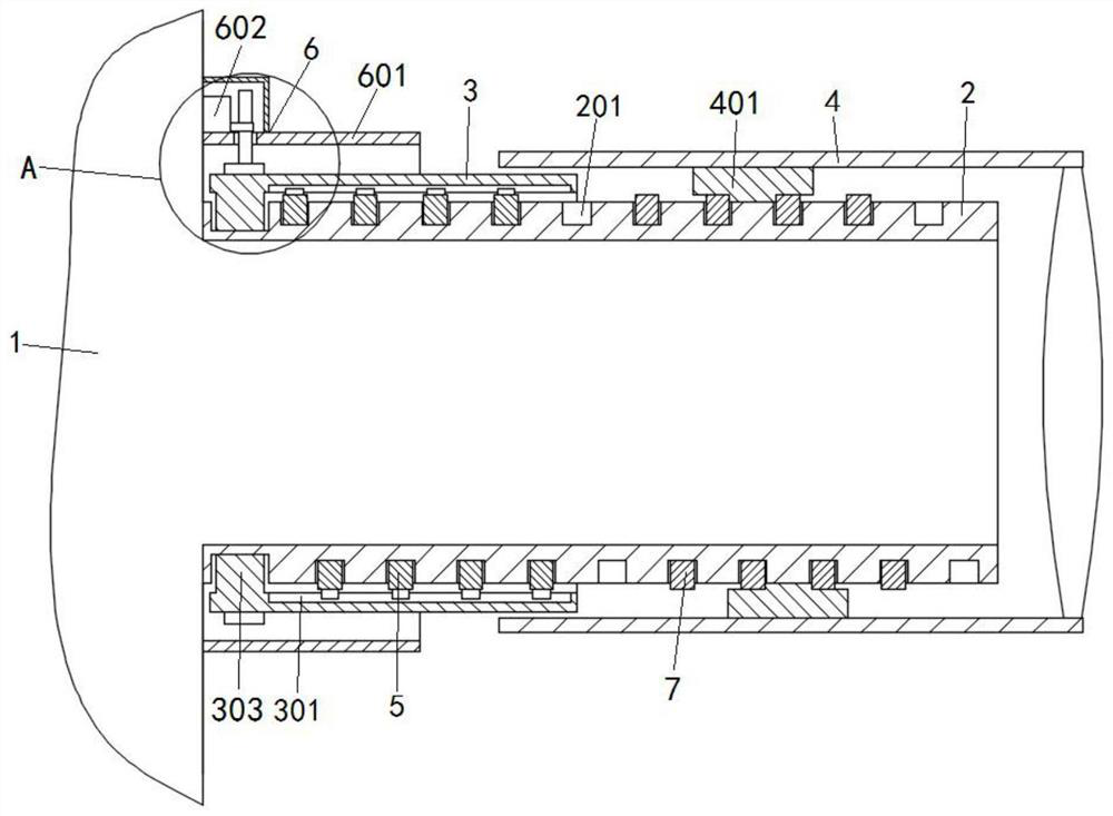
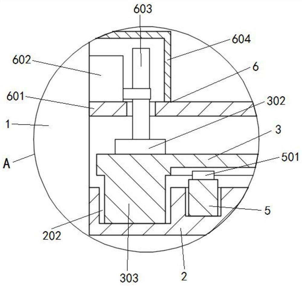
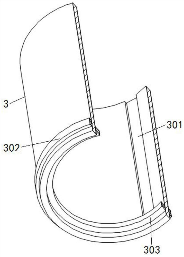
[0004] The object of the present invention is to provide a driving device for a camera lens. The rotating cylinder is driven to rotate through the driving mechanism. Since the sliding groove and the sliding block are slidably matched, the first spiral sliding bar will slide along the spiral sliding groove, and then the second spiral sliding bar will slide along the spiral sliding groove. One spiral slide bar pushes the second spiral slide bar to slide spirally, and finally realizes that the moving cylinder rotates on its own, and moves along the axial direction of the light-incoming inner cylinder to realize the adjustment of the focal length, which solves the inconvenience of manual operation when people take pictures. The troublesome problem caused by adjusting the focal length

Method used


Image

  • A driving device for a camera lens
  • A driving device for a camera lens
  • A driving device for a camera lens

Examples


Embodiment Construction

[0026] The following will clearly and completely describe the technical solutions in the embodiments of the present invention with reference to the accompanying drawings in the embodiments of the present invention. Obviously, the described embodiments are only some, not all, embodiments of the present invention. Based on the embodiments of the present invention, all other embodiments obtained by persons of ordinary skill in the art without creative efforts fall within the protection scope of the present invention.

[0027] In the description of the present invention, it should be understood that the terms "disposition", "open", "end face", "surface", "inner", "circumferential side", etc. indicate orientation or positional relationship, and are only for the convenience of describing the present invention. Inventive and simplified descriptions do not indicate or imply that the components or elements referred to must have a particular orientation, be constructed and operate in a p...


PUM


Abstract

The invention discloses a driving device for a camera lens and relates to the technical field of cameras. The invention comprises a camera body, the side of the camera body is connected with a light-introducing inner cylinder; a spiral chute is opened on the peripheral side of the light-introducing inner cylinder, and the light-introducing inner cylinder is matched with a rotating cylinder and a moving cylinder respectively, and the rotating cylinder is located between the moving cylinder and the moving cylinder. between the camera bodies; wherein, the rotating cylinder is connected to the peripheral side of the light-introducing inner cylinder; a first spiral slide bar is arranged between the rotating cylinder and the light-introducing inner cylinder. The present invention drives the drum to rotate through the driving mechanism. Since the chute is slidingly matched with the slider, the first helical slider will slide along the helical chute, and then the first helical slider will push the second helical slider to helically slide, and finally While realizing the rotation of the moving cylinder, it also moves along the axial direction of the light-incoming inner cylinder to realize the adjustment of the focal length. This adjustment method is simple, and the action of the driving mechanism can be controlled by electronic control, which is convenient for people to take pictures.

Description

technical field [0001] The invention belongs to the technical field of cameras, in particular to a driving device for a camera lens. Background technique [0002] As people's requirements for the quality of life gradually increase, more and more people start to use cameras to preserve the beauty in life; it is often seen that people use cameras to take pictures of beautiful moments in scenic spots or in daily life and work. [0003] And existing camera mostly is that people carry out focusing to the lens of camera by manual adjustment, to shoot whole or partial detail; or angle, which brings some troubles to people's shooting; therefore, a kind of driving device for camera lens is to be studied to improve the efficiency and convenience of people's shooting. Contents of the invention [0004] The object of the present invention is to provide a driving device for a camera lens. The rotating cylinder is driven to rotate through the driving mechanism. Since the sliding groove...

Claims


Application Information

Patent Timeline
Patent Type & Authority Patents(China)
IPC IPC(8): G02B7/04G03B13/34
CPCG02B7/04G03B13/34
Inventor 阚智博
Owner 贵州倍易通科技有限公司
Why Eureka
Try Eureka