
Image electronic device and driving method

A technology of image electronics and images, applied in the direction of instruments, optics, lenses, etc.

Pending Publication Date: 2022-01-11
SEEYA OPTRONICS LTD
View PDF8 Cites 0 Cited by
  • Summary
  • Abstract
  • Description
  • Claims
  • Application Information

AI Technical Summary

Problems solved by technology

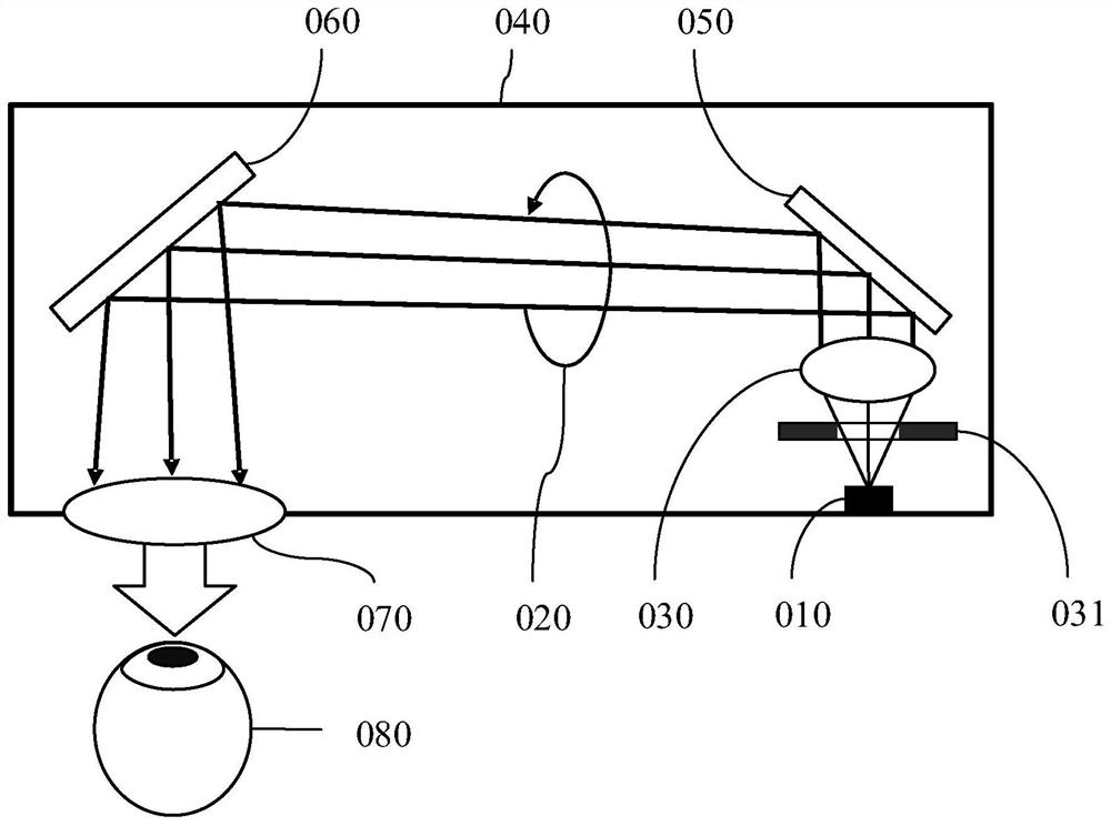
[0008] In the above analysis, only the display device including the display screen and the focusing objective lens is taken as an example to illustrate the shortcomings of the existing image display device. In fact, an image sensing device including an image sensor chip and a focusing lens also has similar problems. Weaknesses and needs for improvement

Method used


Image

  • Image electronic device and driving method
  • Image electronic device and driving method
  • Image electronic device and driving method

Examples


Embodiment Construction

[0032] The present invention will be further described in detail below in conjunction with the accompanying drawings and embodiments. It should be understood that the specific embodiments described here are only used to explain the present invention, but not to limit the present invention. In addition, it should be noted that, for the convenience of description, only some structures related to the present invention are shown in the drawings but not all structures.

[0033] Terms used in the embodiments of the present invention are only for the purpose of describing specific embodiments, and are not intended to limit the present invention. It should be noted that the orientation words such as "up", "down", "left", and "right" described in the embodiments of the present invention are described from the angles shown in the drawings, and should not be interpreted as a reference to the implementation of the present invention. Example limitations. Also in this context, it also nee...


PUM

PropertyMeasurementUnit
refractive indexaaaaaaaaaa

Abstract

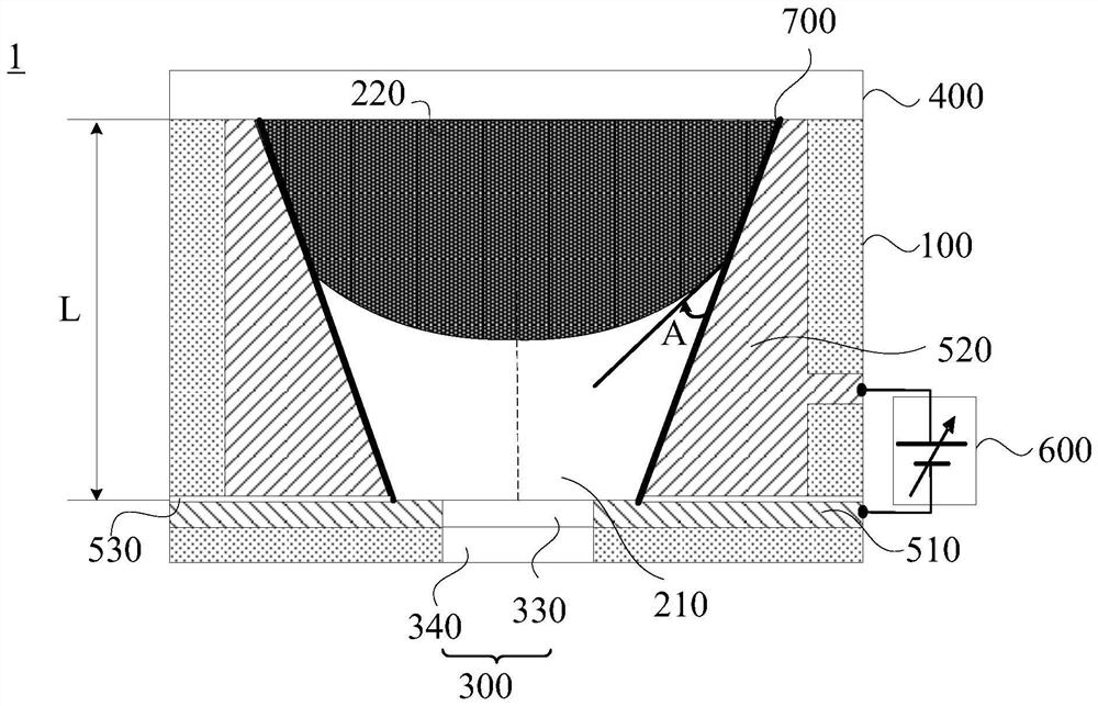
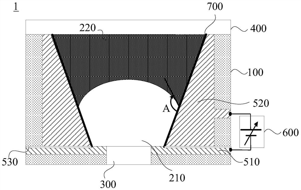
The invention provides an image electronic device and a driving method. The image electronic device comprises a barrel-shaped container; a conductive liquid and an insulating liquid, which have the same density but different optical refractive indexes, are not mutually dissolved and are filled in the barrel-shaped container; an image electronic device, which is positioned at one end of the barrel-shaped container and is in contact with the conductive liquid; a light-transmitting window, which is positioned at the other end of the barrel-shaped container and is in contact with the insulating liquid; a first electrode, which is connected with the conductive liquid; an electric field is formed between the second electrode and the conductive liquid; and a voltage source, which applies a variable voltage between the first electrode and the second electrode. The voltage source can change the shape of the interface of the conductive liquid and the insulating liquid so as to form a variable-focus liquid lens. The liquid lens and the image electronic device are integrated, the light utilization rate is improved, and the image electronic device is miniaturized.

Description

technical field [0001] Embodiments of the present invention relate to display technologies, and in particular to an image electronic device and a driving method. Background technique [0002] With the popularization of silicon-based organic light emitting diode display (OLED: Organic Light Emitting Diode) technology in wearable glasses such as augmented reality (AR: Augment Reality) and virtual reality (VR: Virtual Reality), its high optical performance Performance, miniaturization and light weight of the overall system, and the requirements for the universality and adjustability of different groups of people, and the comfort of wearing for a long time are also getting higher and higher. Unlike glasses for personal use, those produced on the factory assembly line are all standard products, so the glasses must have a means of adjusting the diopter according to the user's vision. Traditional visual optical equipment, such as telescopes and microscopes, are usually adjusted me...

Claims


Application Information

Patent Timeline
Patent Type & Authority Applications(China)
IPC IPC(8): G02B27/01G02B3/14
CPCG02B27/0172G02B3/14G02B26/005G02B26/004G02B26/0875
Inventor 黄忠守
Owner SEEYA OPTRONICS LTD
Learn More