Eureka AIR delivers breakthrough ideas for toughest innovation challenges, trusted by R&D personnel around the world.

Method for machining steam turbine honeycomb seal with electric sparks

A technology of EDM machine tools and steam turbines, which is applied in the processing field of steam turbine air seals, and can solve the problems of low efficiency, high material consumption, and time-consuming segmental processing, etc.

Active Publication Date: 2010-06-02
DONGFANG TURBINE CO LTD
View PDF0 Cites 12 Cited by
  • Summary
  • Abstract
  • Description
  • Claims
  • Application Information

AI Technical Summary

Problems solved by technology

[0006] 1. The electrode feed rate cannot be precisely controlled, and it depends entirely on the experience of the operator, which requires a high level of skill for the operator. Even if it is the same operator, it is impossible to achieve exactly the same operation every time, so the height and dimensional accuracy of the honeycomb belt Low; and because the honeycomb air seal is divided into several arcs and manufactured separately, there will always be errors in the height of the honeycomb strips in each arc. After all the arcs are combined into a circle, the height of the honeycomb strips in each arc is uneven. gear ring
[0007] 2. Since the honeycomb air seal is usually divided into 6-8 arc segments, segmental processing takes a lot of time, low efficiency and long cycle
[0008] 3. The geometric size of the tool electrode is large, the materials used are large, and the cost is high
[0009] 4. The tool electrode is shaped and difficult to process

Method used


Image

  • Method for machining steam turbine honeycomb seal with electric sparks
  • Method for machining steam turbine honeycomb seal with electric sparks
  • Method for machining steam turbine honeycomb seal with electric sparks

Examples


Embodiment Construction

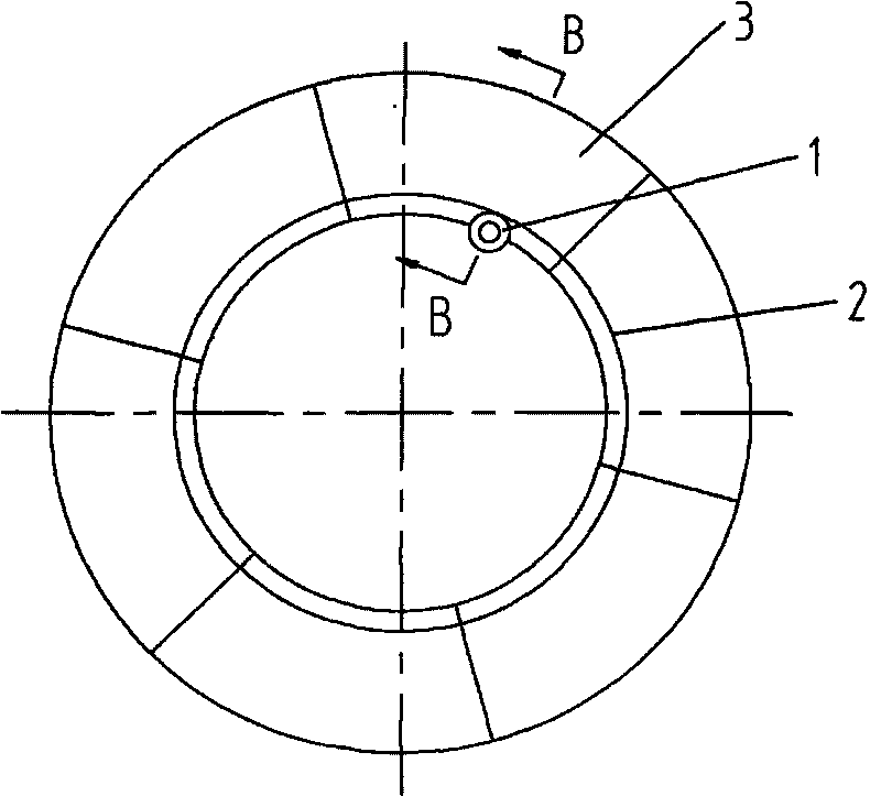
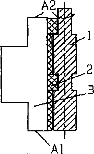
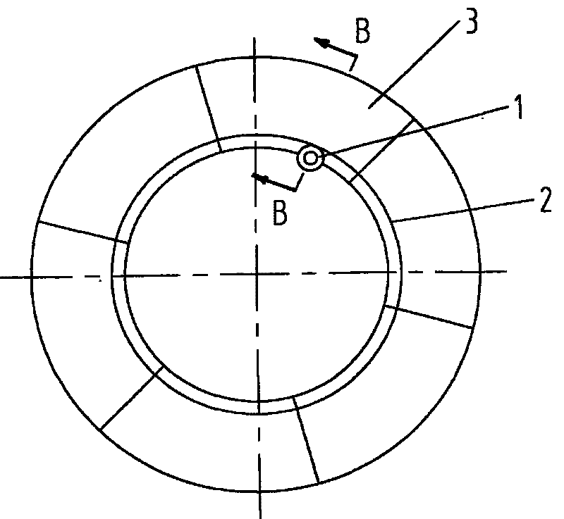
[0024] The key of the present invention is to change the traditional EDM method of feeding the tool electrode in the normal direction relative to the workpiece processing surface, feed along the circumference of the workpiece processing surface, and use the new method of online continuous compensation for electrode wear. This idea is the innovation point of this application, which can solve many problems existing in the traditional electric discharge machining process.

[0025] First of all, the tool electrode is fed along the circumference of the workpiece processing surface, which can greatly simplify the tool electrode structure and facilitate processing; and can greatly reduce its geometric size, reducing material consumption and cost. see figure 2 , the tool electrode 1 used in the present invention has a stepped shaft structure, its contour line is the same as the theoretical contour line of the processing surface, and the peripheral surface of each step is the electrod...


PUM

PropertyMeasurementUnit
thicknessaaaaaaaaaa

Abstract

The invention relates to a method for machining a steam (gas) turbine honeycomb seal with electric sparks. The method comprises the following steps of: manufacturing a tool electrode of which the contour line of the working surface is consistent with the section line of the inner arc surface of a honeycomb band of a honeycomb seal; laying the honeycomb seal on side on a work bench of an electrical discharge machine, aligning, centering and fixing; installing the tool electrode on a main shaft of the electrical discharge machine with the working surface of the tool electrode corresponding to the inner arc surface of the honeycomb band, adjusting the discharging gap, starting the machine to feed the tool electrode along the circumferential direction of the inner arc surface of the honeycomb band, carrying out electro-erosion machining on the inner arc surface of the honeycomb band, and removing chips by radial reciprocating movement when the tool electrode is fed along the circumferential direction. The method for machining a steam turbine honeycomb seal has high accuracy and can enable the contour of the machined working surface of the honeycomb band to be circularly machined. After the seal is assembled into a circle, the steam leakage gap is machined at one time, thereby realizing high efficiency. Besides, the tool electrode has the advantages of small geometric size, little material, simple structure, easy machining and low cost.

Description

technical field [0001] The invention relates to a processing method for a gas seal of a steam turbine, in particular to a method for processing a honeycomb gas seal of a steam (including gas) turbine by electric sparks. Background technique [0002] Steam (including gas) turbines have multiple work stages. Most of the steam (or gas) flows into the steam passages of the moving blades at all levels, expands to do work, impels the blades, and makes the rotor rotate. A small part of the steam (or gas) passes through the surrounding air. The periphery of the belt flows into the lower clapboard, which becomes internal leakage steam (gas) and does not do work. Therefore, a steam (gas) seal is installed on the periphery of the belt to minimize the flow of internal leakage and improve the efficiency of the unit. [0003] The traditional steam (gas, the same below) seal has a toothed structure. The internal leakage flow is limited by rationally designing the gap between the tooth tip ...

Claims


Application Information

Patent Timeline
Patent Type & Authority Applications(China)
IPC IPC(8): B23H1/00B23H9/00
Inventor 尹军黄岚宋冬梅
Owner DONGFANG TURBINE CO LTD
Why Eureka
Eureka Blog
Learn More