Variable pitch control system, variable pitch control method and wind generating set

A pitch motor and control system technology, applied in the pitch field, can solve the problems of maintenance difficulties, difficulties in the development and manufacture of electrical components and mechanical components, unfavorable development of large or super large wind turbines, etc. Beneficial for installation and maintenance

Inactive Publication Date: 2012-10-31
SINOVEL WIND GRP
View PDF9 Cites 12 Cited by
  • Summary
  • Abstract
  • Description
  • Claims
  • Application Information

AI Technical Summary

Problems solved by technology

[0006] For the pitch change of a blade of a large or super-large wind turbine, it is difficult to achieve effective and fast pitch change with a single pitch motor and pitch reducer, and the development and manufacture of its corresponding electrical and mechanical components is also difficult. There are certain difficulties, which not only make the selection and installation of the pitch motor difficult, but also the maintenance in the future is also difficult, which is not conducive to the development of large or super large wind turbines

Method used


Image

  • Variable pitch control system, variable pitch control method and wind generating set
  • Variable pitch control system, variable pitch control method and wind generating set
  • Variable pitch control system, variable pitch control method and wind generating set

Examples


Embodiment 1

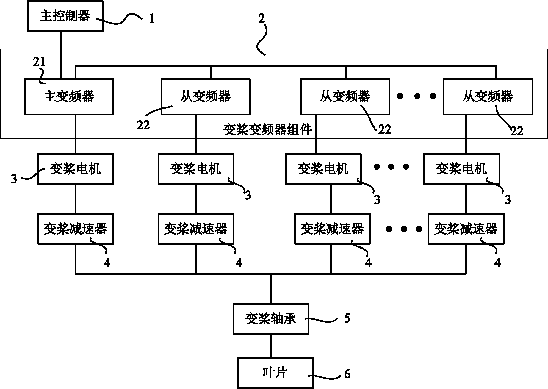
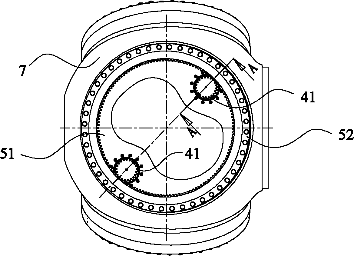
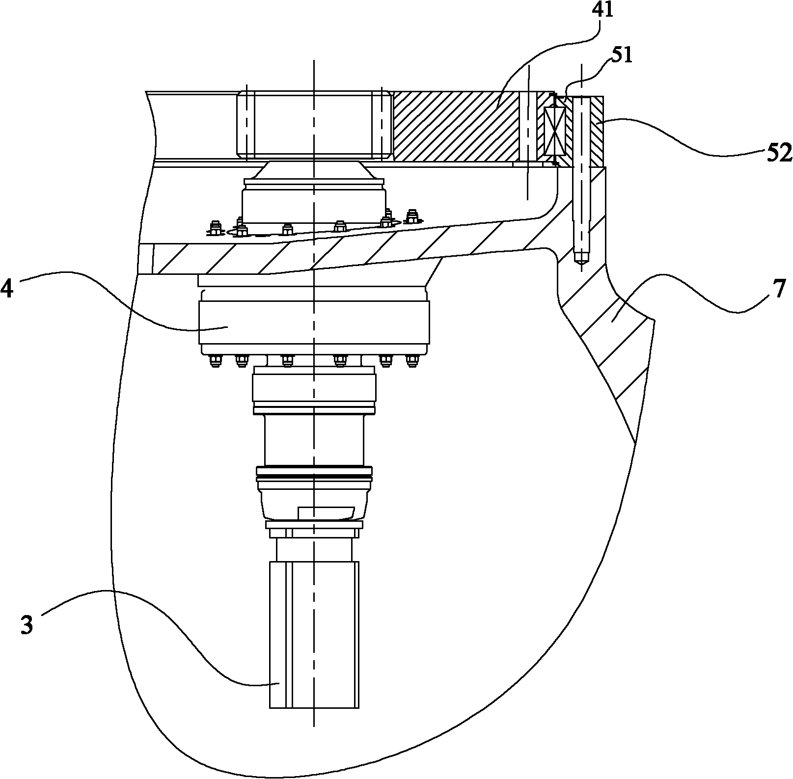
[0040] Embodiment 1 of the present invention provides a pitch control system, figure 1 It is a schematic structural diagram of the pitch control system provided by Embodiment 1 of the present invention, figure 2 It is a schematic diagram of a partial structure of the pitch control system provided by Embodiment 1 of the present invention, image 3 for figure 2 A cross-sectional view of the A-A direction.

[0041] refer to figure 1 , figure 2 with image 3 As shown, the pitch control system includes a main controller 1 , a pitch frequency converter assembly 2 , a pitch motor 3 , a pitch reducer 4 and a pitch bearing 5 .

[0042] There is one pitch bearing 5 set corresponding to each blade 6, and a plurality of pitch motors 3 drive a plurality of pitch reducers 4, and a plurality of pitch reducers 4 mesh with one pitch bearing 5 to drive the pitch reducer 5 respectively. Paddle bearing 5 rotates.

[0043] The pitch frequency converter assembly 2 corresponding to each bl...

Embodiment 2

[0059] Figure 5 A schematic structural diagram of the pitch control system provided by Embodiment 2 of the present invention, as shown in Figure 5 As shown, on the basis of the first embodiment above, the pitch control system is further provided with a first detection module 81 and a first comparison module 91 .

[0060] The first detection module 81 is connected between the pitch motor 3 controlled by the main inverter 21 and the first comparison module 91 , and is used to feed back the detected current position of the pitch motor 3 to the first comparison module 91 .

[0061] The first comparison module 91 is connected with the main frequency converter 21, and is used to compare the current position of the pitch motor 3 with the expected position to generate a deviation signal, and transmit the deviation signal to the main frequency converter 21 to instruct the main frequency converter 21 according to The deviation signal adjusts the setting parameters.

Embodiment 3

[0063] The technical solution of the above-mentioned embodiment 2 is a closed-loop control solution including position feedback of the pitch motor, Image 6 The structural schematic diagram of the pitch control system provided by Embodiment 3 of the present invention adopts the scheme of feedbacking the position of the pitch bearing to form a closed-loop control, as shown in Image 6 As shown, on the basis of the first embodiment above, the pitch control system further includes a second detection module 82 and a second comparison module 92 .

[0064] The second detection module 82 is connected between the pitch bearing 5 and the second comparison module 92 for feeding back the detected current position of the pitch bearing to the second comparison module 92 .

[0065] The second comparison module 92 is connected with the main frequency converter 21, and is used to compare the current position of the pitch bearing 5 with the expected position to generate a deviation signal, and...


PUM


Abstract

The invention discloses a variable pitch control system, a variable pitch control method and a wind generating set. The variable pitch control system comprises a main controller, a variable pitch frequency converter component, variable pitch motors, variable pitch reducers and variable pitch bearings, wherein one variable pitch bearing corresponds to each blade; the plurality of variable pitch reducers are respectively driven by a plurality of variable pitch motor shafts; the plurality of variable pitch reducers are respectively meshed with one variable pitch bearing so as to drive the variable pitch bearing to rotate; and the variable pitch frequency converter component which corresponds to each blade comprises a plurality of frequency converters which comprise a master frequency converter and the rest of slave frequency converters and respectively drive the plurality of variable pitch motors. The variable pitch control on blades of a large or an extra-large wind generating set is realized on the basis of not adding electric and mechanical loads of the variable pitch motors and the variable pitch reducers.

Description

technical field [0001] The present invention relates to the pitch technology, in particular to a pitch control system, a pitch control method and a wind power generating set. Background technique [0002] Wind power converts the kinetic energy of the air into mechanical energy and then into electrical energy. It is currently the fastest-growing and most potential development direction in the field of new energy development. However, wind energy, as an intermittent energy source, has great randomness and uncontrollability. [0003] The output power of wind turbines usually fluctuates in a large range. Usually, the pitch angle of the blades on the hub is adjusted through the pitch control system, and the pitch angle is adjusted at any time according to the change of wind speed to control the wind energy absorbed by the wind turbine, thereby improving the overall wind power generation. The efficiency of the unit can keep the power and speed of the wind turbine stable, and can ...

Claims


Application Information

Patent Timeline
Patent Type & Authority Applications(China)
IPC IPC(8): F03D7/00F03D9/00
CPCY02E10/723Y02E10/72
Inventor 路计庄李磊闫猛
Owner SINOVEL WIND GRP
Why Eureka
Try Eureka