Dotted blind floor tile
A blind road and floor tile technology, applied in the field of dot matrix blind road floor tiles, can solve the problems of too long walking time, inconvenient cleaning, sore and numb feet, etc., and achieve the effect of maintaining sensitivity, good buffering effect, and improving travel safety.
- Summary
- Abstract
- Description
- Claims
- Application Information
AI Technical Summary
Problems solved by technology
Method used
Image

Examples
Embodiment 1
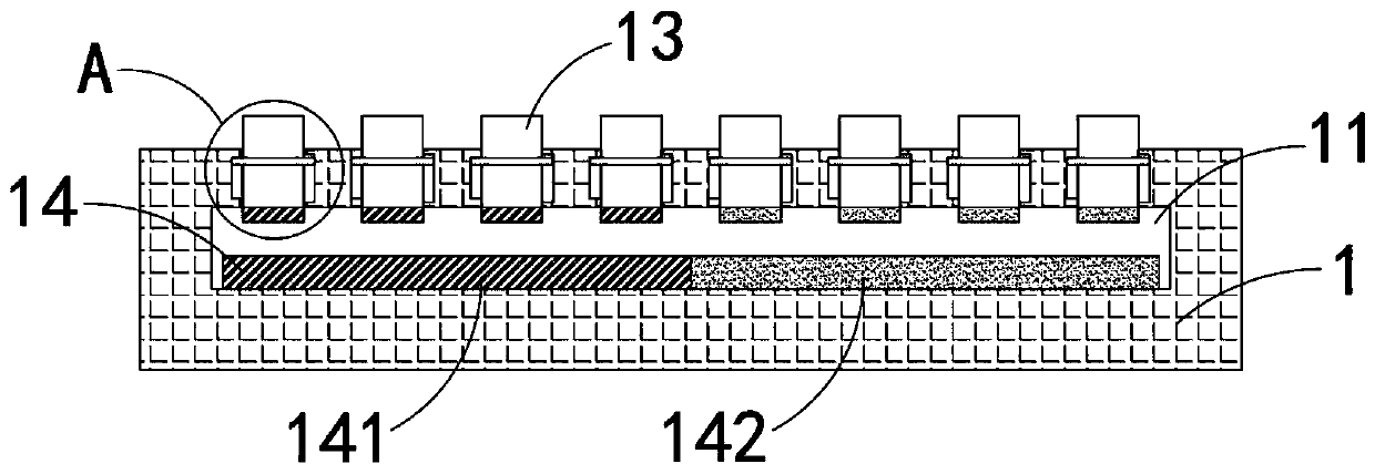
[0038] like Figure 1-3 As shown, a dot-matrix tactile floor tile includes a brick body 1, and the brick body 1 includes:
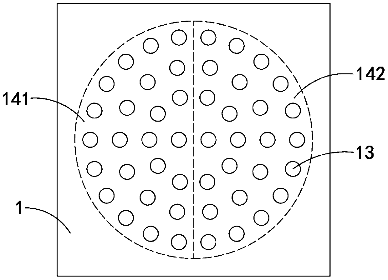
[0039] Storage cavity 11, the storage cavity 11 is a cylindrical cavity, and the storage cavity 11 is arranged in the middle part of the brick body 1;
[0040] A plurality of vertical through holes 12, the plurality of vertical through holes 12 are evenly distributed with the center of the storage cavity 11 as the center of the circle, and the plurality of vertical through holes 12 are all connected to the storage cavity 11;
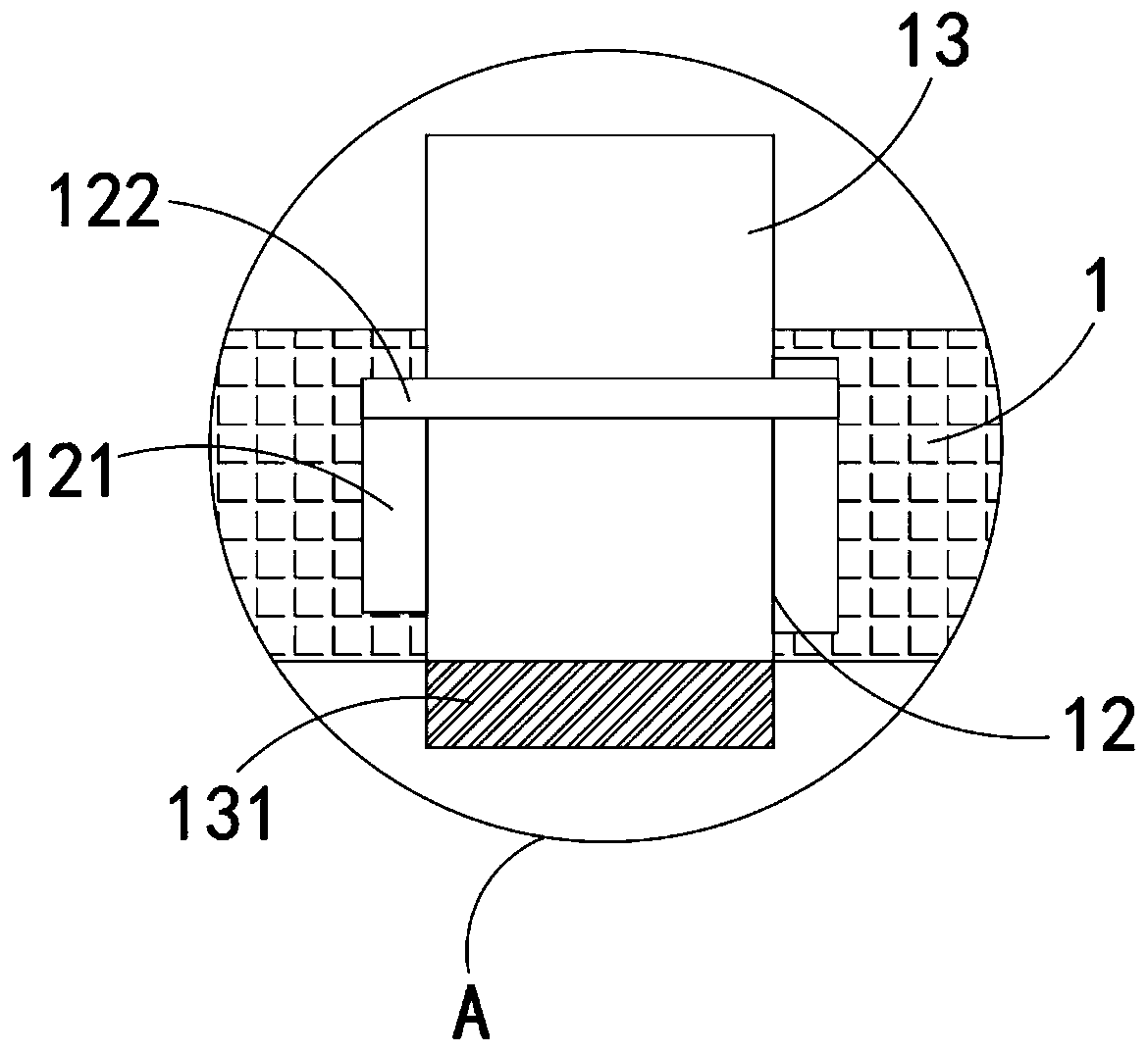
[0041] A plurality of sliding posts 13 correspond one-to-one to a plurality of vertical through holes 12, and the sliding posts 13 are slidably arranged in the vertical through holes 12. It should be noted that the vertical through holes 12 are provided with annular The limiting groove 121, the annular limiting groove 121 is slidingly provided with a limiting ring 122, the limiting ring 122 is fixedly connected on the sliding colum...
Embodiment 2
[0047] like Figure 4 As shown, the difference between this embodiment and Embodiment 1 is that: the storage cavity 11 is provided with:
[0048] The installation groove 111, the installation groove 111 is arranged at the center of the bottom surface of the storage chamber 11;
[0049] Rotating shaft 112, rotating shaft 112 runs through and is fixedly connected at the center of permanent magnet plate 14, the upper end of rotating shaft 112 is connected with the top surface of receiving chamber 11 in rotation, and the lower end of rotating shaft 112 is connected in rotation with the bottom surface of mounting groove 111;
[0050] A coil spring 113, the coil spring 113 is arranged in the installation groove 111, the inner end of the coil spring 113 is fixedly connected with the side wall of the rotating shaft 112, and the outer end of the coil spring 113 is fixedly connected with the side wall of the installation groove 111;
[0051] Annular electromagnet 114, annular electroma...
PUM
 Abstract
Description
Claims
Application Information
 - R&D
- Intellectual Property
- Life Sciences
- Materials
- Tech Scout
- Unparalleled Data Quality
- Higher Quality Content
- 60% Fewer Hallucinations
Browse by: Latest US Patents, China's latest patents, Technical Efficacy Thesaurus, Application Domain, Technology Topic, Popular Technical Reports.
© 2025 PatSnap. All rights reserved.Legal|Privacy policy|Modern Slavery Act Transparency Statement|Sitemap|About US| Contact US: help@patsnap.com