
LED wall washer

A technology of LED wall washer and LED light source, which is applied to the damage prevention measures of lighting devices, cooling/heating devices of lighting devices, lighting and heating equipment, etc. To achieve the effect of uniform and soft light output, novel light distribution method and ideal heat dissipation effect

Inactive Publication Date: 2019-09-27
彭伟
View PDF0 Cites 0 Cited by
  • Summary
  • Abstract
  • Description
  • Claims
  • Application Information

AI Technical Summary

Problems solved by technology

The structure and light distribution method of the existing LED wall washer are relatively traditional and old, the light-emitting angle is narrow, the light-emitting surface is small, the light-emitting effect is average, and the LED light source generally only passes through the light-transmitting cover once and then directly emits light. , the light is not uniform and soft enough, prone to glare and glare, low light utilization rate, low light efficiency, insufficient irradiation intensity, poor luminous effect
In addition, both the LED light source and the driving device will generate heat. There is no isolation measure or structure between the LED light source and the driving device of the existing LED wall washer. The heat between the two is easy to interfere with each other and affect the service life of each other.

Method used


Image

  • LED wall washer
  • LED wall washer
  • LED wall washer

Examples


Embodiment Construction

[0013] It should be understood that the specific embodiments described here are only used to explain the present invention, not to limit the present invention.

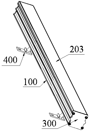
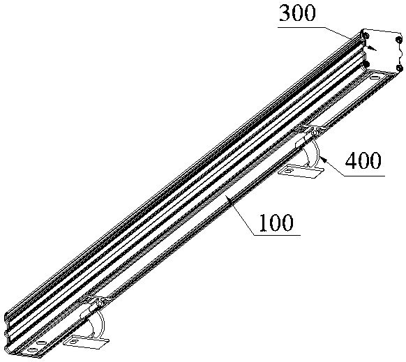
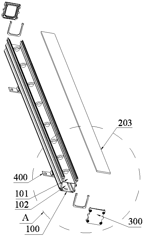
[0014] refer to Figure 1 to Figure 4 , propose an embodiment of an LED wall washer of the present invention, including a heat dissipation lamp housing 100, several LED light sources disposed in the heat dissipation lamp housing 100, and a driver electrically connected to the LED light source located in the heat dissipation lamp housing 100 The device, the light guide and translucent cover 203 installed on the heat dissipation lamp housing 100 to guide and transmit light, the end cover 300 fixed on the end surface of the heat dissipation lamp housing 100 by means of snap-fitting and screwing, is installed on the heat dissipation lamp Mounting bracket 400 at the bottom of case 100 . There is a partition 101 in the middle of the heat dissipation lamp housing 100. The upper end of the partition 101 is a light source cav...


PUM


Abstract

The invention discloses an LED wall washer, which comprises a heat dissipating lamp housing, a plurality of LED light sources arranged in the heat dissipating lamp housing, a driving device arranged in the heat dissipating lamp housing, a light-guide transmitting cover mounted on the heat dissipating lamp housing, an end cover fixed to the end face of the heat dissipating lamp housing, and a mounting frame mounted at the bottom of the heat dissipating lamp housing. A partition plate is arranged in the middle in the heat dissipating lamp housing, the upper end of the partition plate is provided with a light source concave cavity, and the lower end of the partition plate is provided with a hidden chamber; the LED light sources are tightly attached to the upper end face of the light source concave cavity, and meanwhile the driving device is tightly attached to the bottom of the hidden chamber so as to be isolated from the LED light sources to avoid heat disturbance; the heat dissipating lamp housing is of an integrally formed structure and is made of heat-conducting metal; and each LED light source is independently covered with a cylindrical independent lens holder playing a refraction role, the independent lens holders are covered with independent reflecting covers playing a reflective role, the independent reflecting covers are each in an inverted circular truncated cone shape, and the surfaces of the independent reflecting covers are coated with reflective coatings.

Description

technical field [0001] The invention relates to the technical field of lamps, in particular to an LED wall washer. Background technique [0002] Wall washer, as the name suggests, is to let the light wash the wall like water, mainly used for architectural decorative lighting, and to outline the outline of large buildings. Because LED has the characteristics of energy saving, high luminous efficiency, rich colors, and long life, the current wall washer of other light sources is gradually replaced by LED wall washer. The structure and light distribution method of the existing LED wall washer are relatively traditional and old, the light-emitting angle is narrow, the light-emitting surface is small, the light-emitting effect is average, and the LED light source generally only passes through the light-transmitting cover once and then directly emits light. , the light is not uniform and soft enough, prone to glare and glare, the light utilization rate is low, the light efficienc...

Claims


Application Information

Patent Timeline
Patent Type & Authority Applications(China)
IPC IPC(8): F21S8/00F21V19/00F21V8/00F21V17/16F21V15/02F21V7/04
CPCF21S8/00F21V7/04F21V7/22F21V15/02F21V17/164F21V19/001F21V23/003F21V29/507F21V29/89F21Y2115/10
Inventor 王叶彭庆康
Owner 彭伟
Learn More