Liquid control valve

A technology of liquid control and liquid source, applied in valve details, valve devices, valve operation/release devices, etc., can solve problems affecting the working characteristics of piezoelectric actuators, reducing compression ratio, etc.

Inactive Publication Date: 2003-03-12
ROBERT BOSCH GMBH
View PDF1 Cites 0 Cited by
  • Summary
  • Abstract
  • Description
  • Claims
  • Application Information

AI Technical Summary

Problems solved by technology

[0003] In such valves, there is the problem that changes in the length of the piezo actuator, the valve or the valve housing are compensated by the hydraulic coupling chamber
Although the equipment that should carry out this refilling is known from the above-mentioned technical level, it still has deficiencies, and a connection that is constantly opened in two possible flow directions is provided between the coupling chamber and the reserve oil tank. The connection mainly affects the operating characteristics of the piezo actuator
In particular the resulting enlarged volume leads to a reduction in the compression ratio of the transmission rigidity of the hydraulic column formed by the coupling chamber

Method used


Image

  • Liquid control valve
  • Liquid control valve
  • Liquid control valve

Examples


Embodiment Construction

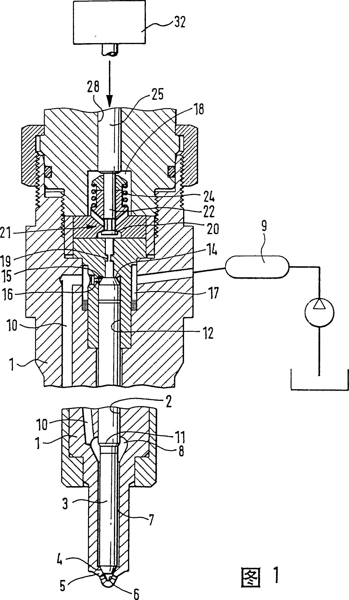
[0011] The valve according to the invention is used on a fuel injection valve, the essential parts of which are shown in section in FIG. 1 of the accompanying drawing. This injection valve has a valve housing 1 in which a valve needle 3 is guided in a longitudinal bore 2, which can also be directed toward Closed direction preload. One end of the valve needle is provided with a tapered sealing surface 4, which cooperates with the valve seat 6 at the tip 5 of the valve housing extending into the combustion chamber. The injection holes are opened behind the valve seat, and these injection holes will spray An annular chamber 7 inside the fuel valve, surrounding the valve needle 3 and filled with fuel under injection pressure, is connected to the combustion chamber in order to inject fuel when the valve needle leaves the valve seat. This annular space is connected to a further pressure space 8 which is continuously connected to a pressure line 10 via which fuel at the injection pr...


PUM


Abstract

The invention relates to a liquid control valve which is provided, for its operation, with a bonding chamber (30) that is filled with liquid and placed between a multiplication piston (35) to be actuated by a piezoelectric element (32) and a piston which actuates a valve member. In order to compensate for a leakage occurring inside the bonding chamber (30) when under high pressure, a charging valve (39) is provided between the multiplication piston (35) and the piezoelectric actuator (32). At each return stroke by the piezoelectric actuator, the multiplication piston follows with a delay time, so that the charging valve (39) opens briefly and enables thereby the bonding chamber to be filled (30). The inventive charging valve is intended for use in fuel injection systems of internal combustion engines for vehicles.

Description

technical field [0001] The present invention relates to a liquid control valve. Background technique [0002] Such a valve is already known from EP 0 477 400 . The control piston of the valve element is sealed and movably arranged on the small-diameter part of the stepped hole, while the large-diameter changing piston moved by the piezoelectric actuator is arranged on the large-diameter part of the stepped hole. A hydraulic chamber is installed between the two pistons in such a way that when the changeover piston moves a certain distance through the actuator, the control piston of the valve element moves a displacement enlarged by the transmission ratio of the stepped bore diameter. The valve element, control piston, large-diameter switching piston and piezo actuator are all located on the same axis. [0003] With such valves, there is the problem that length changes of the piezo actuator, the valve or the valve housing are compensated by the hydraulic coupling chamber. S...

Claims


Application Information

Patent Timeline
Patent Type & Authority Patents(China)
IPC IPC(8): F02M47/02F02M47/00F02M51/00F02M59/46F16K31/00
CPCF02M2200/703F16K31/007F02M63/0026F02M59/46
Inventor 迪特尔·青茨勒克劳斯-彼得·施莫尔弗里德里希·伯金
Owner ROBERT BOSCH GMBH
Why Eureka
Try Eureka