Pipeline flange precision welding device

A technology of precision welding and pipeline flanges, applied in auxiliary devices, welding equipment, auxiliary welding equipment, etc., can solve the problems of weak welding, pipeline leakage, hidden safety hazards, etc., and achieve the effect of facilitating later welding.

Active Publication Date: 2019-10-08
广东网纳智能装备有限公司
View PDF12 Cites 22 Cited by
  • Summary
  • Abstract
  • Description
  • Claims
  • Application Information

AI Technical Summary

Problems solved by technology

[0008] The purpose of the present invention is to overcome the deficiencies of the prior art and provide a precision welding device for pipe flanges, which solves the problem of directly passing the top pressure at both ends to make the flange surface and the end surface of the pipe flush. This welding structure is prone to poor welding. Lead to leakage of the pipeline in the later stage; because the flange is sleeved on the pipeline, there must be a gap between the inner hole of the flange and the outer wall of the pipeline. If the single deposit passes through the top pressure, it is impossible to keep the flange and the pipeline concentric during welding shaft, and it is also difficult to ensure that the side of the flange is perpendicular to the axis of the pipe. If the flange is inclined, there will inevitably be a gap when the pipes at both ends are docked, leaving a safety hazard; and between the pipes They are connected by flanges, and the two flanges are then connected by bolts. In standardized products, if the screw holes of the two flanges on each pipe are not aligned one by one, then when two pipes are connected, there must be two pieces. The screw holes on the connecting flange do not correspond, and the bolts cannot be inserted

Method used


Image

  • Pipeline flange precision welding device
  • Pipeline flange precision welding device
  • Pipeline flange precision welding device

Examples


Embodiment

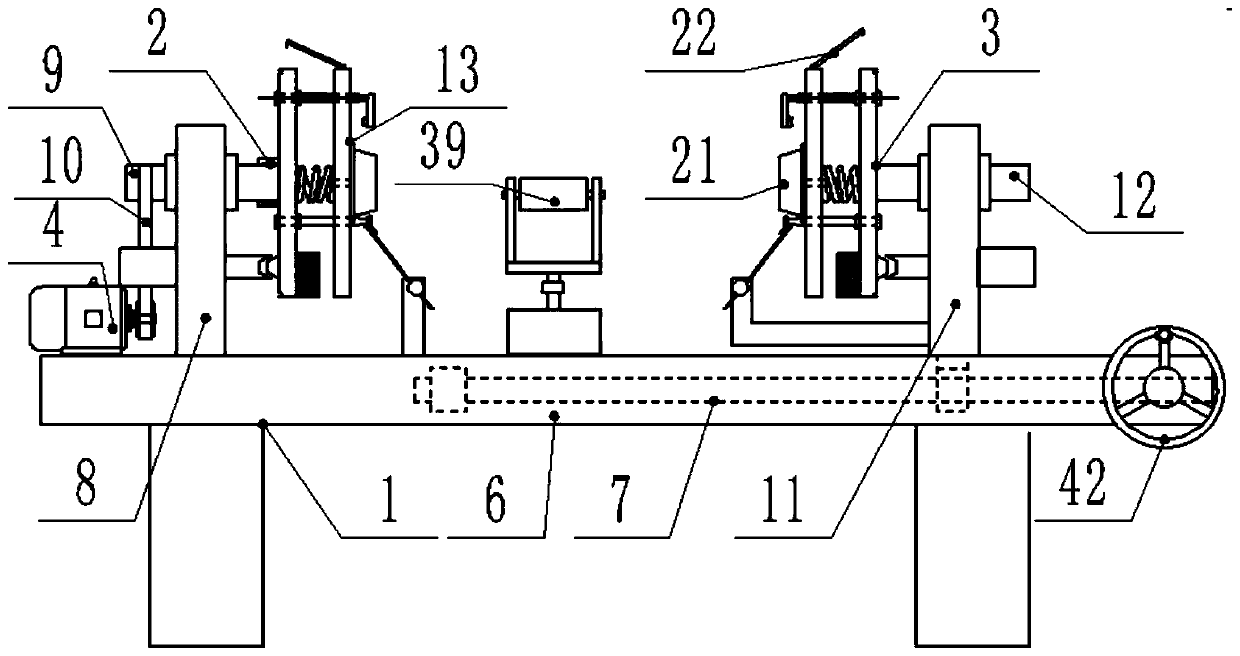
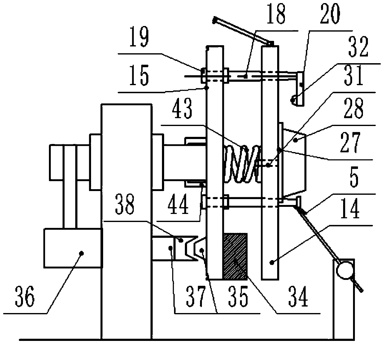
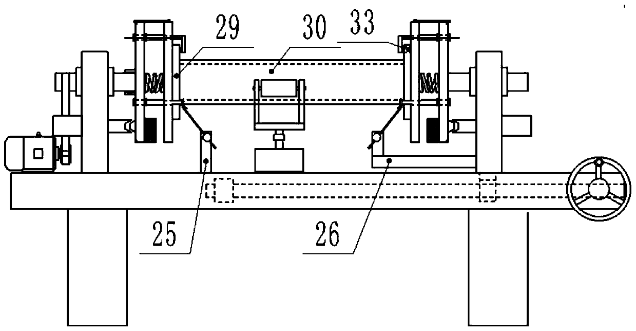
[0045] like Figure 1-8 As shown in the figure, a pipeline flange precision welding device of the present invention includes a welding bench 1, a left flange clamping device 2, a right flange clamping device 3, a drive motor 4 and a welding torch 5. The welding bench 1 is above the welding bench 1. Table 6, welding table 6 is a long structure, which is mainly set according to the length of the pipeline that is often processed. A plurality of legs are arranged under the welding table 6 to form a welding table 1. The welding table 1 is the support structure of the entire welding device. The inside of the right side of the table 6 is provided with a drive screw 7. The drive screw 7 is mainly arranged within the movable range of the right welding stand 11. Both ends of the drive screw 7 are installed through the bearing seat, and the left flange clamping device 2 includes a left welding stand 8, the left welding stand 8 is fixedly arranged on the left side of the welding table 6, ...


PUM


Abstract

The invention discloses a pipeline flange precision welding device. The pipeline flange precision welding device achieves that flange threaded holes of two flange plates welded to one pipeline are automatically aligned in a one-to-one manner, which cannot be achieved in an existing pipeline flange welding technology, and calibration and alignment must be manually conducted inch by inch in the prior art. The flange threaded hole alignment solution provides convenience for follow-up rapid accurate pipeline connection; the pipeline flange precision welding device can be used for welding multipletypes of pipelines and flange plates, it is just need to correspondingly replace matching pipeline centering abutting blocks and matching flange threaded hole calibration conical bosses; the pipelineflange precision welding device can guarantee precision welding of the pipeline flanges and suitable for the nuclear power industry, the chemical industry, the building industry and the industry having high pipeline connection and seal intensity requirements.

Description

technical field [0001] The invention relates to the technical fields of chemical, construction and petroleum pipeline processing and installation equipment, in particular to a pipeline flange precision welding device. Background technique [0002] Common transportation pipelines are usually spliced ​​by a large number of pipelines. Both ends of each pipeline are welded with flanges. Each pipeline is connected by flanges. The flange connection is convenient, firm and tight. It is widely used in the connection of pipelines. [0003] In the prior art, there are many equipments and technologies for welding flanges on pipes, and the degree of automation is quite high. For example, the technical scheme with the patent number 201410267726.1 can realize automatic installation and automatic welding. [0004] However, there are still many technical problems that are difficult to solve in the above-mentioned similar equipment; [0005] 1. According to industry standards, in general o...

Claims


Application Information

Patent Timeline
Patent Type & Authority Applications(China)
IPC IPC(8): B23K37/047B23K37/00B23K37/02B23K37/053
CPCB23K37/00B23K37/02B23K37/047B23K37/0533
Inventor 何艳杨洋
Owner 广东网纳智能装备有限公司
Why Eureka
Try Eureka