A method for realizing precise welding of pipes and flanges

A welding method and flange technology, which is applied in the field of precise welding of pipes and flanges, can solve problems such as weak welding, inability to insert bolts, and non-corresponding screw holes of two connecting flanges

Active Publication Date: 2020-11-17
江苏飞达不锈钢有限公司
View PDF8 Cites 0 Cited by
  • Summary
  • Abstract
  • Description
  • Claims
  • Application Information

AI Technical Summary

Problems solved by technology

[0008] The purpose of the present invention is to overcome the deficiencies of the prior art and provide a method for realizing precise welding of pipes and flanges, which solves the problem of directly pressing both ends to make the flange surface and the end surface of the pipe flush. This welding structure is prone to welding failures If the flange is set on the pipe, there will inevitably be a gap between the inner hole of the flange and the outer wall of the pipe. If only the top pressure is used, it will not be possible to keep the flange and the pipe in place during welding. Concentric axis, and it is difficult to ensure that the side of the flange is perpendicular to the axis of the pipe. If the flange is inclined, there will inevitably be a gap when the pipes at both ends are connected, leaving a safety hazard; The two flanges are connected by flanges, and the two flanges are connected by bolts. In standardized products, if the screw holes of the two flanges on each pipe are not aligned one by one, then two pipes must be connected. The screw holes on the connecting flange of the parts do not correspond, and the bolts cannot be inserted

Method used


Image

  • A method for realizing precise welding of pipes and flanges
  • A method for realizing precise welding of pipes and flanges
  • A method for realizing precise welding of pipes and flanges

Examples


Embodiment

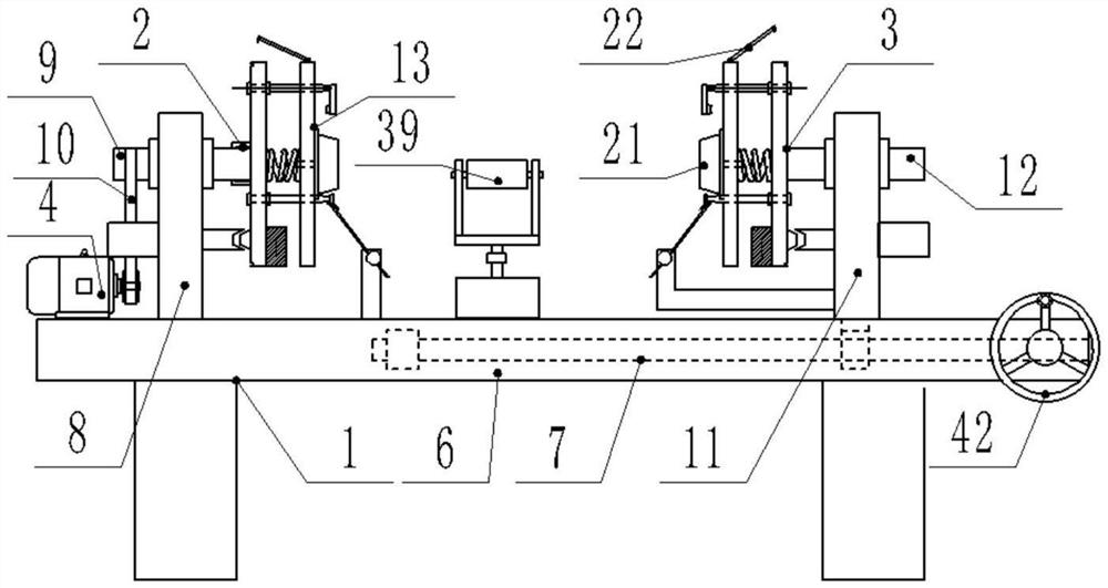
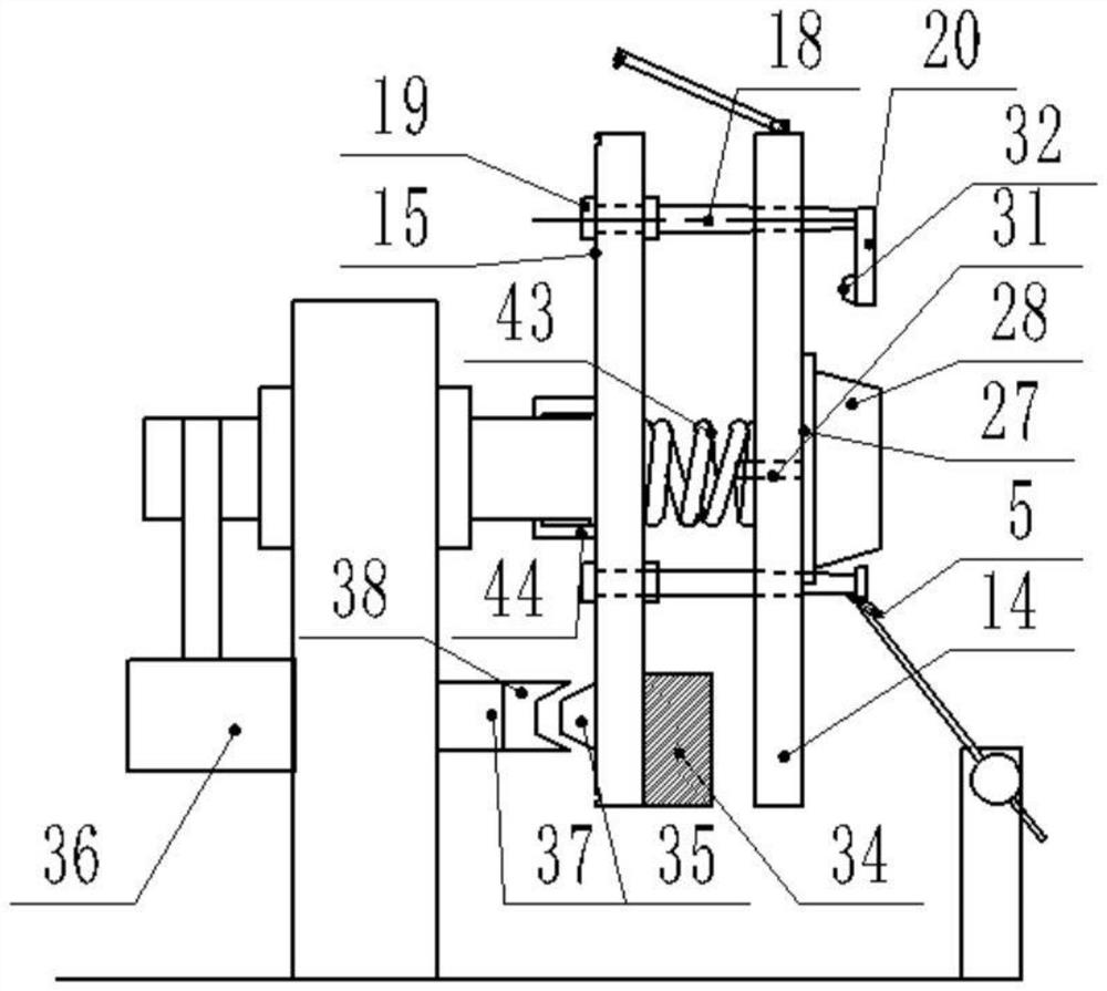
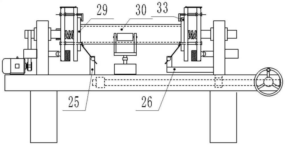
[0048] Such as Figure 1-9 As shown, the present invention realizes a method for precise welding of pipes and flanges, which is characterized in that it comprises steps:

[0049] Above the welding support frame 1 is a welding table 6, and a drive screw 7 is arranged horizontally inside the right side of the welding table 6. The left flange clamp 2 includes a left welding stand 8, and the left welding stand 8 is fixedly arranged. On the left side of the welding table 6, a left welding rotating shaft 9 is horizontally arranged on the left welding stand 8, and the outer end of the left welding rotating shaft 9 is connected with the drive motor 4 arranged on the welding table 6 through a belt 10. The right method The blue clamp 3 includes a right welding stand 11, which is slidably installed on the welding table 6, and the lower end of the right welding stand 11 is screwed with the transmission screw 7, and the right welding stand is controlled by rotating the transmission screw 7...


PUM


Abstract

The invention discloses a method for realizing accurate welding between a pipeline and flanges. The method comprises the following steps that accurate matching and calibration between flange screw hole alignment frustums and flange screw hole calibration tapered holes are achieved, so that flange screw holes in the two flange plates on one pipeline are accurately aligned; then the pipeline is placed between two flange clamping devices, a transmission screw rod is controlled to rotate by rotating a hand wheel disc, and then a right welding vertical frame is driven to move towards a left welding vertical frame on a welding table so as to press the pipeline; then an air cylinder and a telescopic arm are controlled to retract, and then a driving motor and a welding gun are sequentially started for welding; and welding is completed, the pipeline is disassembled, and then next welding is carried out. According to the method, the flange screw holes of the two flange plates welded on one pipeline are automatically aligned one by one, precise welding of the pipeline and the flanges can be guaranteed, and the method can be used in industries needing high requirements for pipeline connection and sealing strength, such as nuclear power, chemical engineering or construction.

Description

technical field [0001] The invention relates to the technical field of sewage treatment equipment pipeline connection, harmful gas treatment equipment pipeline connection and oil pipeline processing and installation equipment, and in particular to a method for realizing precise welding of pipelines and flanges. Background technique [0002] Common transportation pipelines are usually spliced ​​by a large number of pipes. Flanges are welded at both ends of each pipe, and the pipes are connected by flanges. The flange connection is convenient, firm and tight, so it is called Widely used in the connection of pipelines. [0003] In the prior art, there are many equipment and technologies for welding flanges on pipelines, and the degree of automation is quite high. For example, the technical solution with patent number 201410267726.1 can realize automatic installation and automatic welding. [0004] But above-mentioned similar equipment also has a lot of technical problems that ...

Claims


Application Information

Patent Timeline
Patent Type & Authority Patents(China)
IPC IPC(8): B23K31/02B23K37/047
CPCB23K31/02B23K37/047
Inventor 何艳杨洋
Owner 江苏飞达不锈钢有限公司
Why Eureka
Try Eureka