Vehicle lighting module with overlapping light patterns
a technology of vehicle lighting and overlapping light patterns, applied in the direction of transportation and packaging, semiconductor devices for light sources, lighting and heating apparatus, etc., can solve the problems of increasing manufacturing costs, difficult to realize a unified design, and degrading the appearance, so as to reduce manufacturing costs
- Summary
- Abstract
- Description
- Claims
- Application Information
AI Technical Summary
Benefits of technology
Problems solved by technology
Method used
Image
Examples
first embodiment
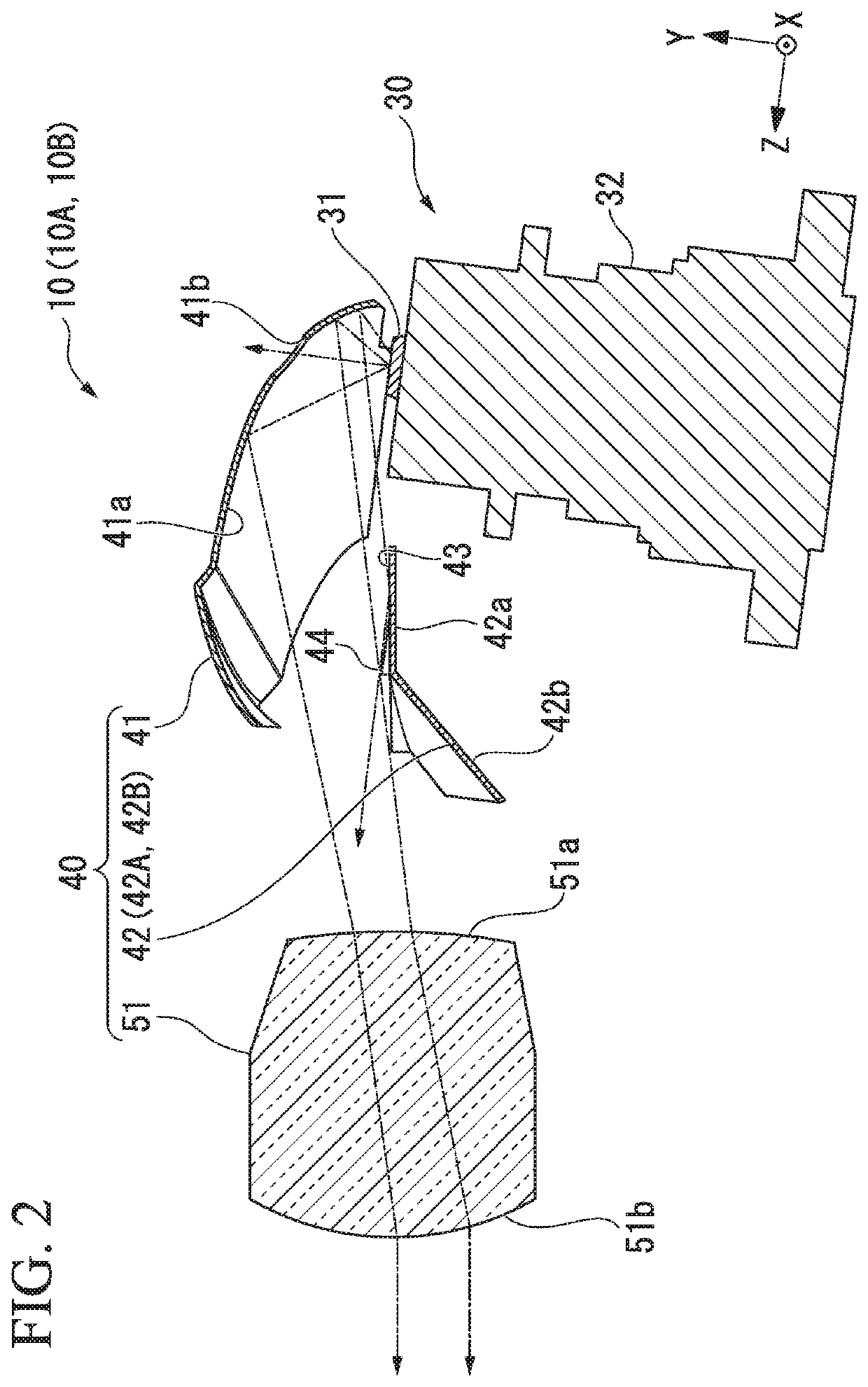
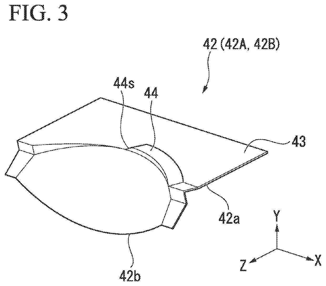
[0034]A vehicle lighting module 1 of a first embodiment of the present invention will now be described with reference to the drawings.
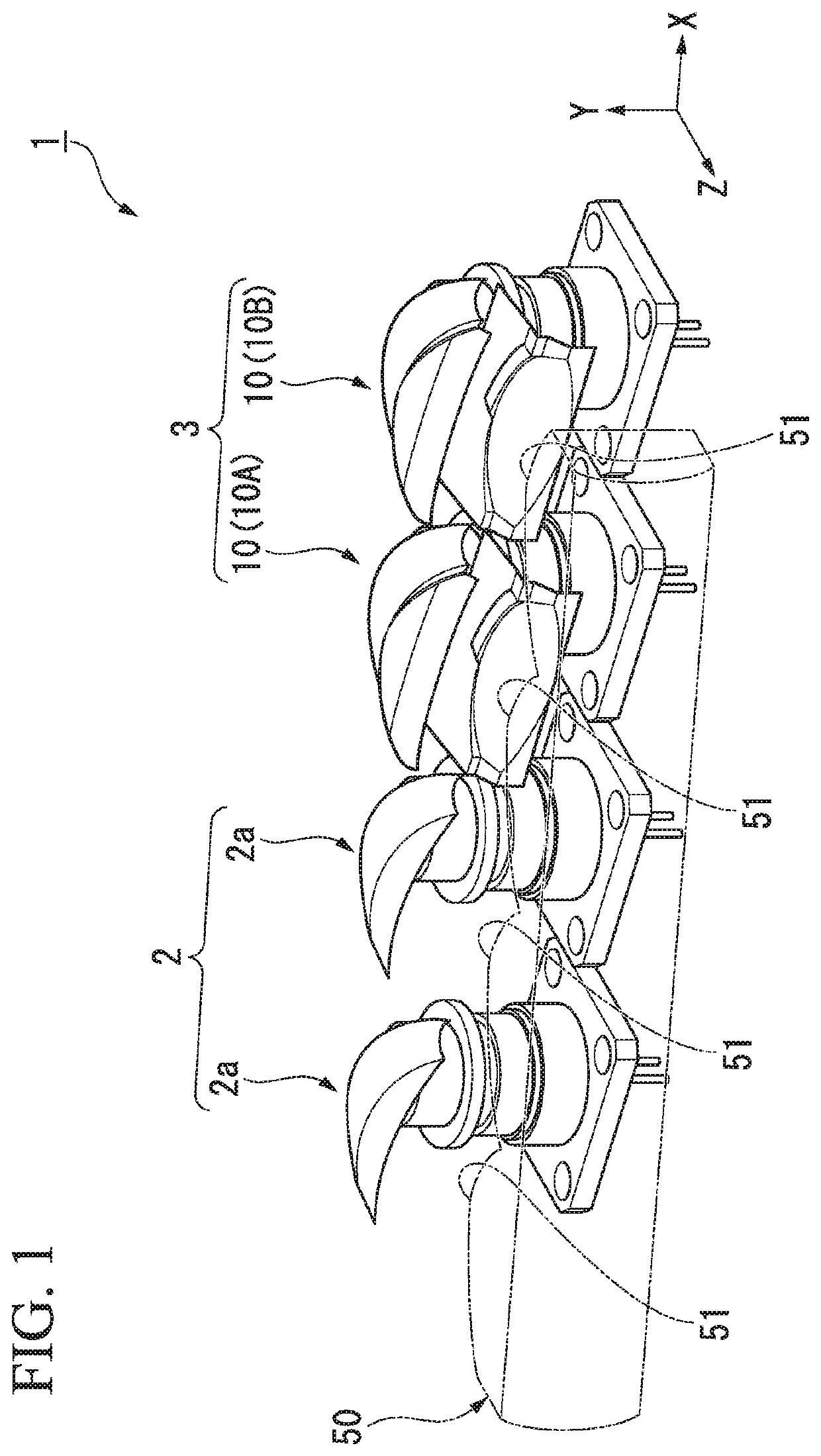
[0035]FIG. 1 is a perspective view of the vehicle lighting module 1 of the first embodiment. The vehicle lighting module 1 is one of a pair of headlamps mounted on the left and right sides of a left-side traveling vehicle and only light source portions and optical parts (such as lenses and reflectors) thereof are shown.
[0036]An XYZ coordinate system is used as a 3-dimensional orthogonal coordinate system in some of the drawings used to explain the present embodiment. In the XYZ coordinate system, the Z-axis direction is a direction parallel to the optical axis of the vehicle lighting module 1, the X-axis direction is a direction parallel to the lateral direction of a vehicle on which the vehicle lighting module 1 is mounted, and the Y-axis direction is a direction perpendicular to both the Z-axis and X-axis directions. The Z-axis direction will someti...
second embodiment
[0069]A vehicle lighting module of a second embodiment will now be described with reference to the drawings. The vehicle lighting module of the second embodiment has substantially the same configuration as that of the first embodiment described above but with different configurations of light distribution patterns formed.
[0070]FIGS. 7a and 7b are schematic views showing light distribution patterns PD and PE formed by two optical units (corresponding to the first and second optical units 10A and 10B of FIG. 1), respectively, of the vehicle lighting module of the second embodiment. FIG. 7c is a schematic view of a combined light distribution pattern PF formed by overlapping the light distribution patterns PD and PE. Elements similar to those of the above embodiment are denoted by the same reference numbers and descriptions thereof are omitted here.
[0071]As shown in FIG. 7a, a straight cutoff line CLD is formed at an upper end edge (or at an end edge of one of the upper and lower sides...
third embodiment
[0082]A vehicle lighting module of a third embodiment will now be described with reference to the drawings. The vehicle lighting module of the third embodiment has substantially the same configuration as that of the first embodiment described above but with different configurations of light distribution patterns formed.
[0083]FIG. 8 is a schematic view of a combined light distribution pattern PI formed by overlapping first and second light distribution patterns PG and PH which are formed by two optical units (corresponding to the first and second optical units 10A and 10B of FIG. 1) of the vehicle lighting module of the third embodiment. Elements similar to those of the above embodiments are denoted by the same reference numbers and descriptions thereof are omitted.
[0084]The first light distribution pattern PG has, at an upper end edge thereof, a first cutoff line CLG1 and a second cutoff line CLG2 which are formed at different vertical levels. An inclined line L is formed between th...
PUM
 Abstract
Description
Claims
Application Information
 - R&D
- Intellectual Property
- Life Sciences
- Materials
- Tech Scout
- Unparalleled Data Quality
- Higher Quality Content
- 60% Fewer Hallucinations
Browse by: Latest US Patents, China's latest patents, Technical Efficacy Thesaurus, Application Domain, Technology Topic, Popular Technical Reports.
© 2025 PatSnap. All rights reserved.Legal|Privacy policy|Modern Slavery Act Transparency Statement|Sitemap|About US| Contact US: help@patsnap.com


