

Inner tension wall
A tension and wall technology, applied in the direction of walls, building components, ceilings, etc., can solve problems such as cost increase, complex construction, dirty environment, etc., and achieve the effect of reducing the use of manpower and material resources, saving decoration costs, and shortening decoration time.
- Summary
- Abstract
- Description
- Claims
- Application Information
AI Technical Summary
Problems solved by technology
Method used
Image

Examples
Embodiment 1
[0082] Example 1: Double-sided partition wall
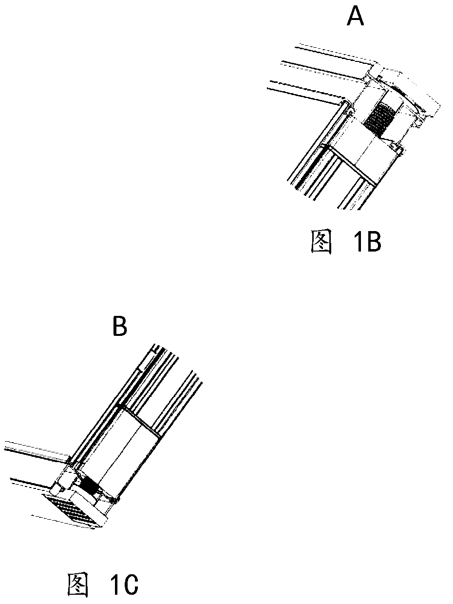
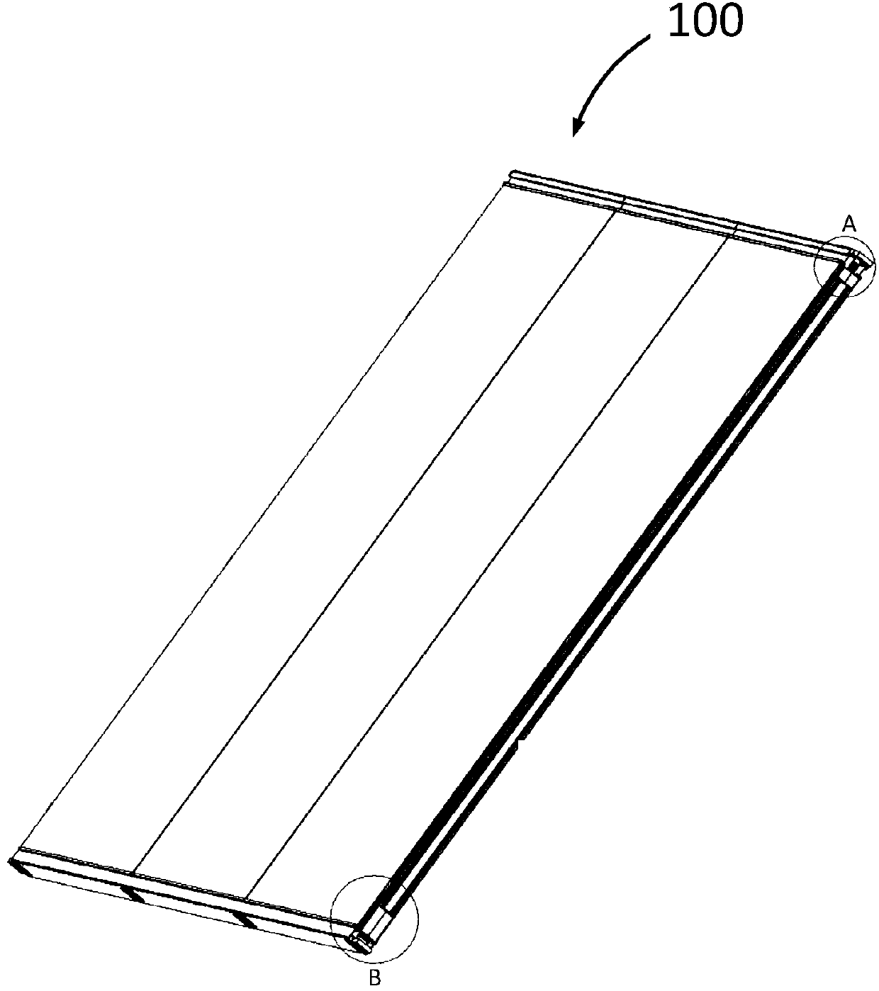
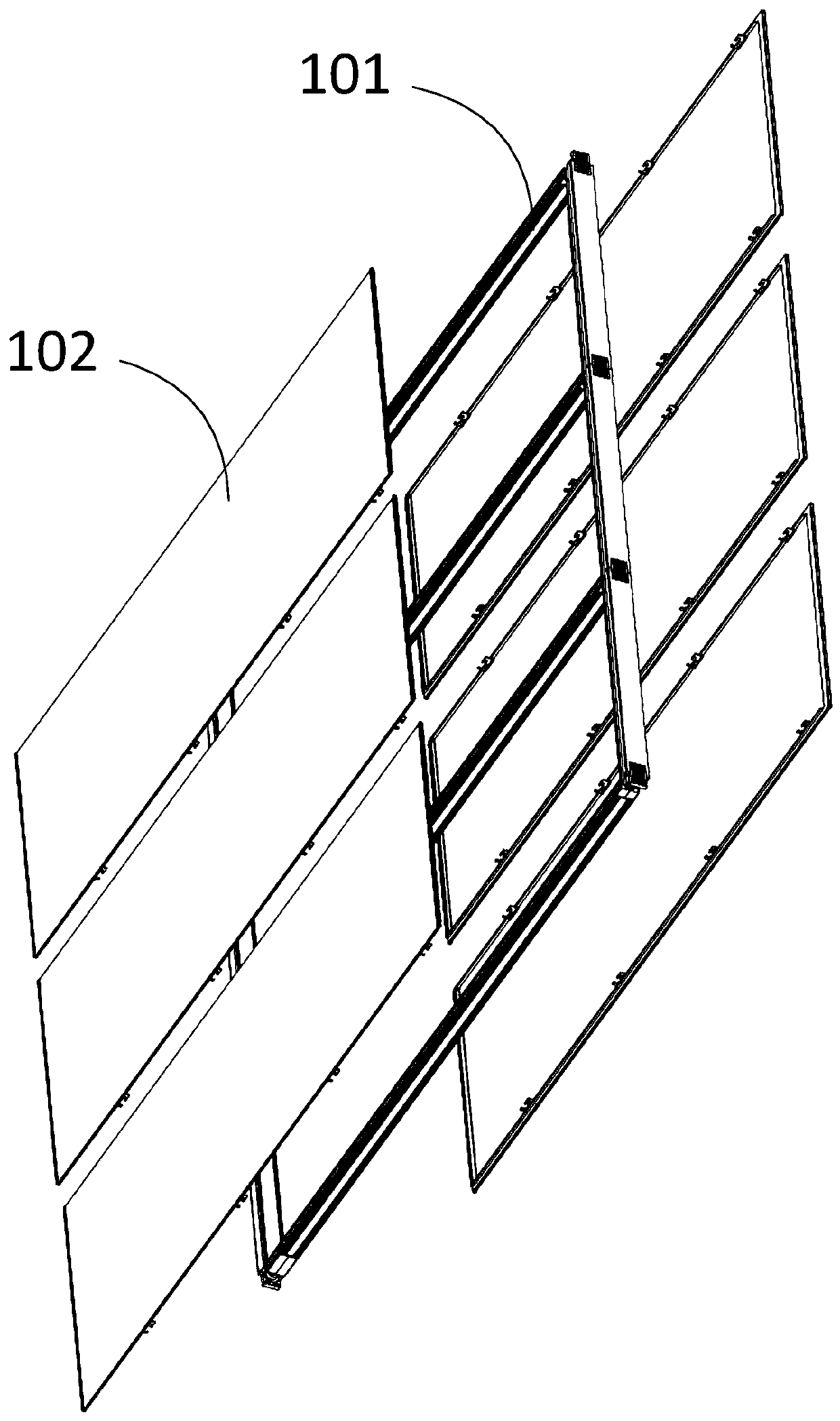
[0083] Figure 1A-Figure 1C It is a structural schematic diagram of a wall according to an embodiment of the present invention. in, Figure 1A is a three-dimensional view of the wall, showing its overall shape; Figure 1B It is a partial enlarged view of wall A, showing a corner of the wall; Figure 1C It is a partial enlarged view of wall B, showing the other corner of the wall. figure 2 is an exploded view of a wall according to one embodiment of the present invention. exist figure 2 The installation relationship of its various components is shown in .
[0084] As shown, the wall 100 has an overall rectangular shape. The wall 100 includes a frame 101 and a plurality of mounts 102 mounted on the frame 101. The height of the frame 101 is roughly equivalent to the height of the room, and is suitable for detachable installation between environmental objects. A plurality of hanging objects 102 are respectively hung on tw...
Embodiment 2
[0146] Example 2: Single-sided partition wall
[0147] Figure 13A-Figure 13H It is a structural schematic diagram of a wall according to another embodiment of the present invention. Figure 13A It is a three-dimensional view of the front of the wall, showing its overall shape; Figure 13B-Figure 13D It is a partial enlarged view of the front of walls A, B, and C. Figure 13E It is a three-dimensional view of the back of the wall, showing its overall shape; Figure 13F-Figure 13H It is a partial enlarged view of the back of walls A, B, and C. Figure 14A and Figure 14B is an exploded view of a wall according to another embodiment of the present invention. Figure 14A It is the exploded view of the front of the wall; Figure 14B is an exploded view of the back of the wall; in Figure 14A and Figure 14B The installation relationship of its various components is shown in .
[0148] As shown, wall 1300 includes a plurality of walls, each generally generally rectangula...
Embodiment 3
[0205] Example 3: Integral Partition Wall
[0206] Figure 23 It is a structural schematic diagram of a wall according to another embodiment of the present invention.
[0207] As shown, the wall 2300 has an overall rectangular shape. Wall 2300 includes one or more body portions 2301 and tension members 2302. Wherein, the tension component includes two states, in the first state, there is a propping force between the tension component and the environmental object, and in the second state, there is no propensity between the tension component and the environmental object. According to an embodiment of the present invention, a plurality of main body parts stand side by side in the environment object. According to one embodiment of the invention, the main body part may not be in contact with the existing walls of the room. For example: the main part is only in contact with the ceiling and the floor, or only one side of the main part is in contact with the existing walls of th...
PUM
 Abstract
Description
Claims
Application Information