
Organic electroluminescent device

An electroluminescent device and a luminescent technology, applied in the direction of electric solid-state devices, electrical components, semiconductor devices, etc., can solve the problems of unbalanced carrier injection, low device service life and work efficiency, and achieve the purpose of suppressing self-doping , Improve the service life and work efficiency

Active Publication Date: 2019-10-08
WUHAN CHINA STAR OPTOELECTRONICS SEMICON DISPLAY TECH CO LTD
View PDF4 Cites 0 Cited by
  • Summary
  • Abstract
  • Description
  • Claims
  • Application Information

AI Technical Summary

Problems solved by technology

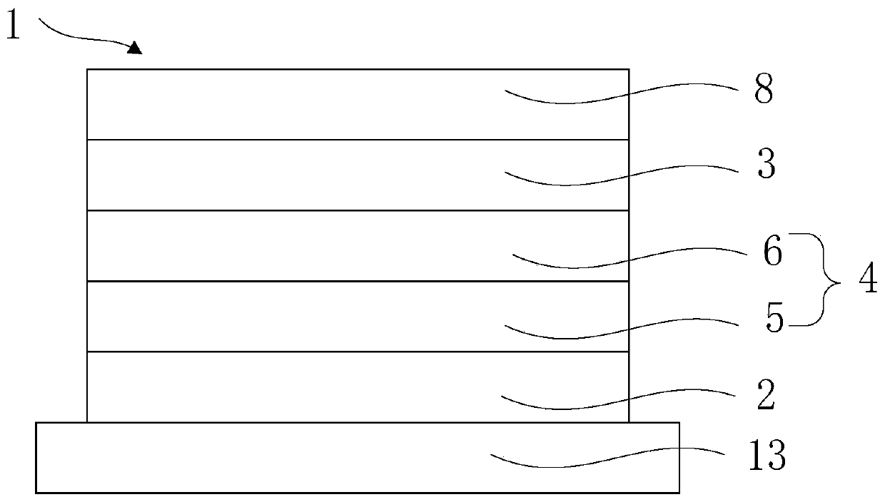
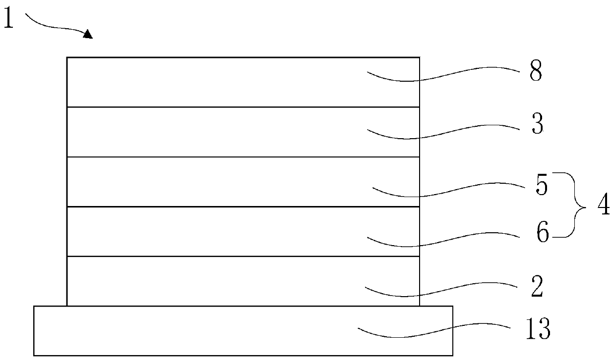
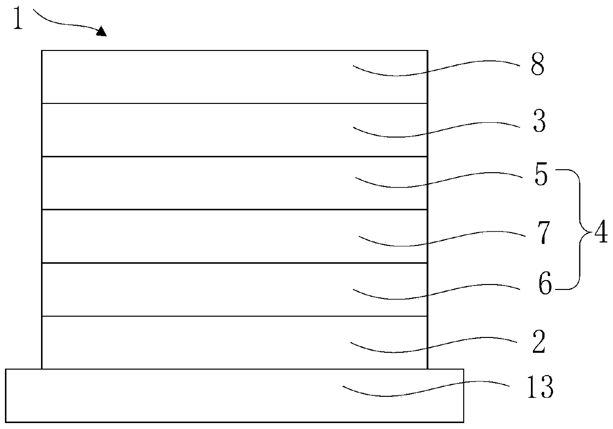
[0004] The embodiment of the present application provides an organic electroluminescent device to solve the imbalance of carrier injection in the organic electroluminescent device and the service life of the device caused by self-doping of the N-type doped electron transport layer during the evaporation process of the cathode Technical issues related to low productivity

Method used


Image

  • Organic electroluminescent device
  • Organic electroluminescent device
  • Organic electroluminescent device

Examples


Embodiment Construction

[0031] Specific structural and functional details disclosed herein are representative only and are for purposes of describing example embodiments of the present application. This application may, however, be embodied in many alternative forms and should not be construed as limited to only the embodiments set forth herein.

[0032] In the description of this application, it should be understood that the terms "central", "lateral", "upper", "lower", "left", "right", "vertical", "horizontal", "top", The orientation or positional relationship indicated by "bottom", "inner", "outer", etc. is based on the orientation or positional relationship shown in the drawings, and is only for the convenience of describing the application and simplifying the description, rather than indicating or implying the referred device Or elements must have a certain orientation, be constructed and operate in a certain orientation, and thus should not be construed as limiting the application. In addition...


PUM


Abstract

The invention discloses an organic electroluminescent device. The organic electroluminescent device includes an anode, a cathode opposite to the anode, and a light emitting function layer arranged between the anode and the cathode, wherein the light emitting function layer includes a light emitting layer and a PB junction layer arranged at one side of the light emitting layer, when the anode is electrified with positive electricity and the cathode is electrified with negative electricity, the PN junction layer forms an open circuit to balance the rate at which the cathode and the anode injectcarriers into the light emitting layer. The organic electroluminescent device is advantaged in that the PN junction layer can suppress excessive injection of the carriers with a fast migration rate, electrons injected into the light emitting layer from the cathode and holes injected into the light emitting layer from the anode are made to be in an equilibrium state, and improvement of the servicelife and work efficiency of the organic electroluminescent device is facilitated.

Description

technical field [0001] The present application relates to the technical field of display panels, in particular to an organic electroluminescent device. Background technique [0002] Organic light emitting diode (OLED) has the advantages of self-illumination, ultra-thin, low power consumption, high contrast, and can be applied to flexible displays, and has received extensive attention and research in the display industry. Low-voltage, high-efficiency, and long-life OLEDs are the key indicators for their application in the display industry. The design and synthesis of OLED materials and the reasonable collocation of device structures are effective ways to improve efficiency, reduce voltage, and increase life. [0003] Most of the OLEDs used in flat panel displays are top-emitting OLEDs (Top-emitting OLEDs, TEOLEDs). When the transport capabilities of electrons and holes in TEOLEDs differ greatly, the injection of carriers (including electrons and holes) The large difference i...

Claims


Application Information

Patent Timeline
Patent Type & Authority Applications(China)
IPC IPC(8): H01L51/50
CPCH10K50/11H10K50/18H10K50/16H10K50/156H10K50/155H10K50/166H10K50/165H10K50/171
Inventor 丁可
Owner WUHAN CHINA STAR OPTOELECTRONICS SEMICON DISPLAY TECH CO LTD
Learn More