Aviation connector for integrated connection device
A technology of integrated access and aerial insertion, applied in aerial insertion. It can solve the problems of accidental touch, increase the difficulty of maintenance, breakage of wires and air plug interfaces, etc.
- Summary
- Abstract
- Description
- Claims
- Application Information
AI Technical Summary
Problems solved by technology
Method used
Image
Examples
Embodiment 1
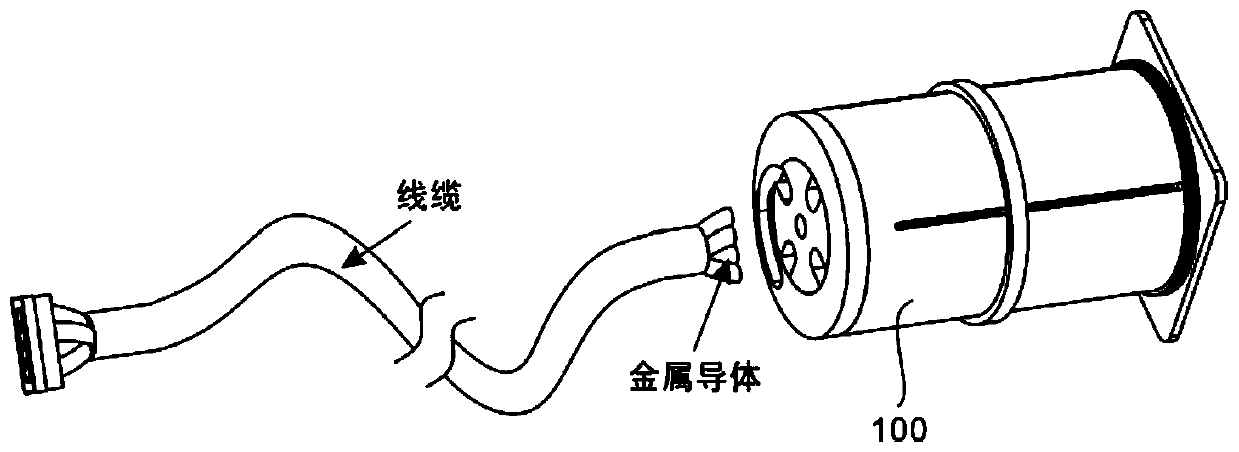
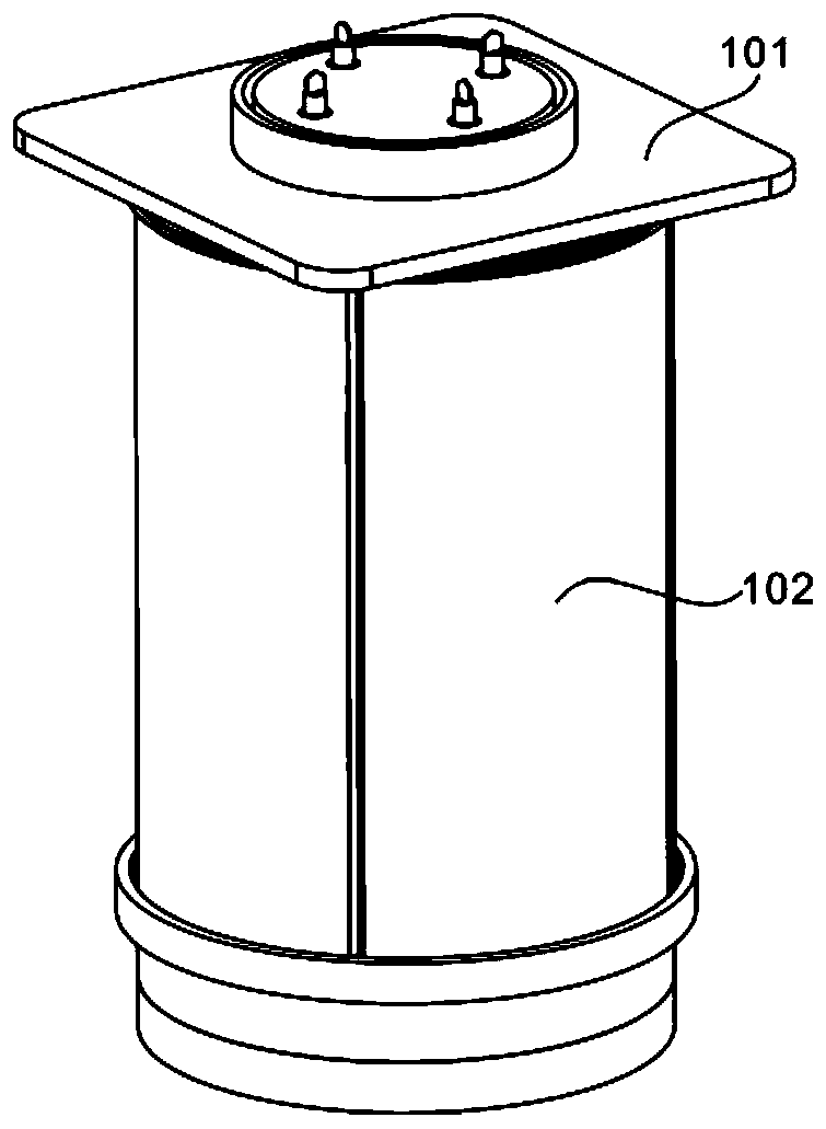
[0032] refer to figure 1 , 2 and 5, as the first embodiment of the present invention, provide an aviation plug for an integrated access device, this device includes a housing 100 and a connector 200, wherein the housing 100 includes a wire barrel 101 and an aviation plug panel 102, the wiring barrel 101 is arranged on the back of the aviation plug-in panel 102; the connector 200 includes a wire pulling unit 201 and a fastening unit 202, the wire pulling unit 201 is connected to the fastening unit 202, and the wire pulling unit 201 and the fastening unit 202 are connected to the wiring On the inner cavity and the side wall of the cylinder 101.
[0033] Wherein, the housing 100 is used for receiving the connector 200 and arranging the wires in the connecting cable, and the connector 200 is used for pairing and connecting the conductors in the aviation plug-in panel 102 and the conductors in the cable. The wiring barrel 101 is a housing for installation, and its top is connecte...
Embodiment 2
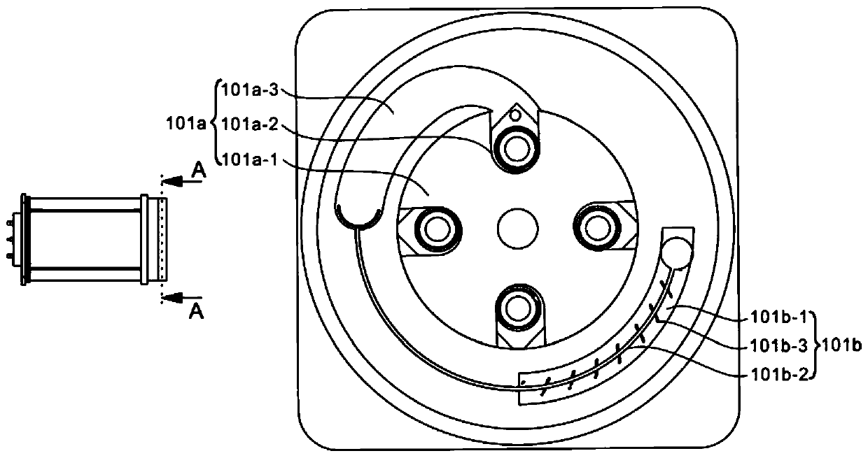
[0036] refer to image 3 , is the second embodiment of the present invention, this embodiment is different from the first embodiment in that: the wire barrel 101 includes a guide groove unit 101a and a wire pushing unit 101b, and the guide groove unit 101a and the wire pushing unit 101b are both arranged on The end of the wire barrel 101 away from the aviation plug-in panel 102, wherein the guide groove unit 101a is rotatably connected to the middle of the end face of the wire barrel 101, and the wire pushing unit 101b is arranged outside the guide groove unit 101a, and both are arranged in the same plane.
[0037] Compared with Embodiment 1, further, the middle part of the free end surface of the wire barrel 101 is provided with a groove, the guide groove unit 101a is installed inside the groove, and the wire pushing unit 101b is located outside the side wall of the groove, wherein the guide groove The unit 101a is used for arranging and distributing the wires in the cable, and...
Embodiment 3
[0041] refer to image 3 , is the third embodiment of the present invention, and this embodiment is different from the second embodiment in that: the guide groove unit 101a includes a wire plate 101a-1, a wire slot 101a-2 and a wire groove 101a-3, and the wire plate The middle part of 101a-1 is rotatably connected to the middle part of the end face of the wire barrel 101, the edge of the side wall of the wire plate 101a-1 is provided with a wire groove 101a-2, and the wire groove 101a-3 is opened outside the side wall of the wire plate 101a-1, Its notch matches with the wire slot 101a-2.
[0042] Compared with Embodiment 2, further, the wire plate 101a-1 is circular, and its middle is rotatably connected in the groove at the end of the wire barrel 101, and the radial diameter of the groove is slightly larger than the diameter of the wire plate 101a-1. The wire grooves 101a-2 are evenly distributed on the edge side wall of the wire plate 101a-1, and the size of the slot hole o...
PUM
 Abstract
Description
Claims
Application Information
 - R&D
- Intellectual Property
- Life Sciences
- Materials
- Tech Scout
- Unparalleled Data Quality
- Higher Quality Content
- 60% Fewer Hallucinations
Browse by: Latest US Patents, China's latest patents, Technical Efficacy Thesaurus, Application Domain, Technology Topic, Popular Technical Reports.
© 2025 PatSnap. All rights reserved.Legal|Privacy policy|Modern Slavery Act Transparency Statement|Sitemap|About US| Contact US: help@patsnap.com


